
Radial and Axial Load Capacity of Crossed Roller Bearings
A crossed roller bearing carries load through cylindrical rollers set at 90 degrees to one another in alternating sequence between the inner and outer rings. Because the rollers are oriented at a 45 degree contact angle to the bearing axis, a single bearing set resists radial forces, axial forces in both directions, and tilting moments at the same time. That versatility is the reason crossed roller bearings appear in rotary tables, robot joints, machine tool spindles and indexing heads. It is also the reason their radial and axial load capacity must be evaluated together rather than separately, since both load components pass through the same contact.
The Load Path Inside a Crossed Roller Bearing
Each roller contacts the raceways along a line rather than at a point. Line contact, combined with a large number of rollers spread across the full circumference, produces a stiff, high-capacity interface that distributes load evenly and limits deflection under reversing or oscillating motion.
The 45 degree contact angle is the defining feature. A force applied radially and a force applied axially of equal magnitude generate the same normal load at the contact. As a result, catalogue static ratings for radial and axial capacity in crossed roller bearings are usually of a similar order of magnitude, and the limiting factor is often not the raceway itself but the roller end faces, the guiding surfaces, or the rigidity of the surrounding structure.
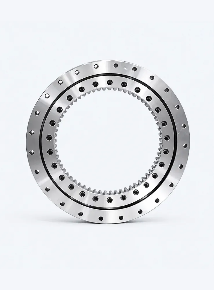
Why the Alternating Arrangement Matters
- Alternating rollers resist moment loads that would separate the rings in a single-row design.
- Spacer retainers keep the rollers from skewing, which preserves the designed load path.
- The compact cross section means the bearing can be integrated into a housing without a separate thrust bearing.
Radial Load Capacity: What Actually Limits It
Radial capacity is governed by the number of rollers in contact, the effective roller length, the raceway hardness and surface finish, and the accuracy of the mounting surfaces. The theoretical rating published in a catalogue assumes ideal conditions: full 360 degree support from a rigid housing, uniform contact, and no edge loading.
Preload, Clearance and Stiffness
Preload does not raise the static radial capacity of a crossed roller bearing. What it does is eliminate clearance, distribute load across more rollers at low external loads, and increase stiffness. The trade-off is a higher normal load at the contact for a given external force, which shortens fatigue life. Clearance produces the opposite effect: lower friction and easier rotation, but a smaller number of rollers carrying the load and greater deflection under reversing loads.
The Role of the Housing
A thin-walled or flexible housing can deflect under load and transfer the force unevenly to a portion of the roller set. In practice, the radial capacity achieved in a real assembly is frequently lower than the catalogue figure because of housing deflection, poor flatness of the mounting face, or a shaft that bends under load.
…
For more detailed information regarding the radial and axial load-carrying capacities of crossed roller bearings, please click here: https://www.bobibearing.com/a/bearing-knowledge/crossed-roller-bearings-radial-and-axial-load-capacity.html


