What is the manufacturing process of thin section bearings?

The manufacturing process of thin section bearings is a complex and precision-driven endeavor, often more challenging than that of standard bearings due to their extremely thin cross-sections and precise tolerance requirements.

Thin section bearings manufacturing process

thin section bearings

1. Raw Material Selection:

High-quality steel alloys are typically chosen for their strength, durability, and wear resistance. Common materials include chrome steel (100Cr6) and stainless steel (X65Cr13, 440C).

For demanding applications, specialized materials like high nitrogen steel (X30CrMoN15-1) for corrosion resistance or ceramic (silicon nitride) for balls (reducing friction and improving heat resistance) may be used.

Cage materials vary, including pressed steel, machined bronze, fabric-reinforced phenolic material, or high-performance plastics like PEEK or Polyamide-imide.

2. Forging (for bearing rings):

This is the initial step for creating the basic shape of the inner and outer rings.

For larger sizes and thin-section bearing rings with a small aspect ratio, a “combined forging” method is often used, where two or more blanks are forged together. After rough grinding, they are separated by wire cutting. This reduces processing difficulty, minimizes deformation, saves material, and improves efficiency.

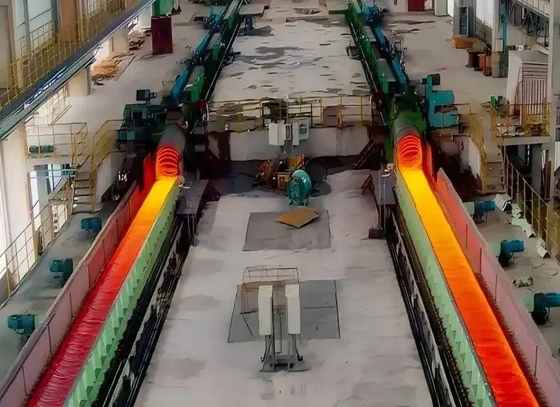
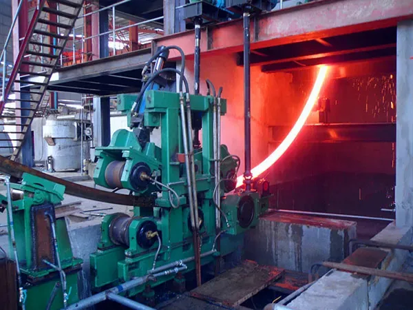
The steel is typically heated to high temperatures (e.g., 1200 degrees Celsius), buckled, pierced, and milled.

Smaller rings might be cut directly from tubes or bars.

3. Turning Process:

Once the basic ring blanks are formed, they undergo precision machining on multi-spindle lathes.

This step involves removing material to create the precise inner and outer dimensions, including the raceways for the rolling elements and grooves for seals.

Due to the thin cross-section and poor rigidity of thin-section bearings, clamping and positioning are critical to avoid deformation. Manufacturers often use specialized fixtures (e.g., multi-point clamping chucks with a large envelope circle contact area) and adjust cutting parameters (e.g., high-speed cutting, small back cutting amount, larger main deflection angle) to minimize machining stress, thermal deformation, and vibration.

An additional tempering process after rough turning may be applied to eliminate stress.

4. Heat Treatment:

This crucial step enhances the strength, hardness, and wear resistance of the bearing components.

Parts are heated in a hardening furnace (e.g., to 800-830 degrees Celsius) and then rapidly cooled, or “quenched,” by immersing them in a salt or oil bath.

During this process, the internal structure of the steel undergoes phase transformation (e.g., austenite to martensite), leading to volume expansion and internal stress.

Die quenching is often used to control deformation. If die quenching isn’t feasible, methods like comprehensive shaping and tempering are used to correct excessive outer diameter deformation.

thin section bearings

5. Grinding and Honing (Fine Grinding):

After heat treatment, the bearing components are ground to their precise final dimensions. This involves using specialized grinding machines and various grinding media.

The goal is to achieve extremely smooth and accurate raceway surfaces for optimal performance and minimal friction.

Multiple fine adjustments of the machine tool are often required for the outer diameter surface.

For more detailed information on the manufacturing process of thin section bearings, please click here: https://www.lynicebearings.com/a/blog/thin-section-bearings-manufacturing-process.html

How does graphite felt performs as insulation in vacuum furnaces?

Graphite felt is a widely used and highly effective insulation material in vacuum furnaces, particularly for high-temperature applications. Here’s a breakdown of its characteristics, advantages, and considerations.

What is Graphite Felt?

Graphite felt is a fibrous material made from carbon fibers that have been subjected to high-temperature graphitization processes. It can be manufactured from various precursor materials like polyacrylonitrile (PAN) or rayon. The “felt” structure, often needle-punched, gives it a low density and high porosity, which are crucial for its insulating properties. There are typically two forms:

Soft Graphite Felt: Flexible and can be shaped around furnace walls.

Rigid Graphite Felt (or cured graphite felt): Made by impregnating soft felt with resin, then curing and graphitizing it to create self-supporting shapes.

Graphite Felt

How it Performs as Insulation in Vacuum Furnaces:

Graphite felt excels as insulation in vacuum furnaces due to several key properties:

Excellent Thermal Insulation: Its low density and porous, fibrous structure create numerous small air gaps (or vacuum gaps in a vacuum furnace) that significantly impede heat transfer by conduction. This results in very low thermal conductivity, especially at high temperatures. Compared to graphite board, graphite felt has significantly lower thermal conductivity, leading to less heat loss.

High-Temperature Stability: Graphite is an allotrope of carbon, and in a vacuum or inert atmosphere, it can withstand extremely high temperatures (up to 3000°C or even higher) without melting or significant degradation. It even exhibits an increase in strength as temperatures rise.

Low Thermal Mass: Its lightweight nature means it absorbs less heat, allowing the furnace to reach operating temperatures faster and cool down more quickly, contributing to energy efficiency and shorter cycle times.

Good Thermal Shock Resistance: Graphite felt can withstand rapid temperature changes without cracking or deforming, maintaining its structural integrity in demanding furnace environments.

Chemical Inertness: In non-oxidizing atmospheres (vacuum or inert gas), graphite is highly resistant to many chemicals and corrosive media, which is crucial in preventing contamination of processed materials.

Ease of Maintenance and Installation: Soft graphite felt is relatively easy to cut, shape, and replace, making repairs and modifications simpler compared to rigid board materials. It can also be maneuvered around mounting points and nozzles.

Graphite Felt

Advantages of Graphite Felt Insulation:

Energy Efficiency: Low thermal conductivity minimizes heat loss, reducing energy consumption and operating costs.

Faster Cycle Times: Low thermal mass allows for quicker heating and cooling, improving productivity.

For more details on how does graphite felt performs as insulation in vacuum furnaces, please click here:https://www.czgraphite.com/a/news/graphite-felt-for-vacuum-furnace-insulation.html

What are the maintenance tips for graphite crucibles in foundries?

Graphite crucibles are essential tools in foundries and metal casting operations, prized for their excellent thermal conductivity, high-temperature resistance, and chemical stability. These crucibles are commonly used for melting and holding non-ferrous metals such as aluminum, copper, brass, and precious metals. Despite their durability, graphite crucibles are still vulnerable to damage from thermal shock, improper handling, and poor maintenance practices.

Maintenance Tips for Graphite Crucibles in Foundries

Graphite Crucibles

1. Proper Handling and Storage:

Inspect upon receipt: Carefully check new crucibles for any chips, cracks, or abrasions. Never use a damaged crucible. A “ring test” with a hammer can help identify internal cracks (a clear bell-like sound indicates no damage, a dull thud might mean mishandling).

Handle with care: Graphite crucibles are durable under heat but can be brittle when cold. Always use properly fitting tongs and lifting equipment to avoid physical damage. Avoid dropping or stacking them directly inside each other.

Store in a dry environment: Moisture absorption is a primary enemy of crucibles. Store them in a dry, warm place, off the floor. If they’ve been exposed to humidity, thoroughly dry them before use. Some recommend storing them in a sealed container with a desiccant.

Avoid rolling: Never roll crucibles, as this can damage the protective glaze.

Protect surfaces: Don’t expose crucibles to substances that can react with graphite or the crucible’s binding materials, such as certain strong acids, alkalis, or specific metal compounds.

2. Crucial Preheating Procedures:

Eliminate moisture: This is perhaps the most critical step. New crucibles, or those that have cooled completely or been exposed to a humid environment, must be preheated to remove all absorbed moisture. Failure to do so can lead to thermal shock, cracking, or even bursting due to steam expansion.

Gradual heating: Start at a low temperature and gradually increase it. A typical preheating cycle might involve:

Heating slowly to 200°C (390°F) to eliminate moisture (hold for at least 20 minutes, or longer for larger crucibles, rotating if possible for even heating).

Increasing the temperature to 600°C (1110°F) on low power.

Then increasing to a bright red heat (around 850-950°C) and holding for 30-60 minutes to develop the protective glaze.

Preheat with the furnace: Ideally, place the crucible in the furnace as it heats up to ensure uniform temperature distribution.

Continuous use: If a crucible is used continuously, it usually doesn’t need to be preheated again between melts unless it has cooled significantly or absorbed moisture.

Graphite Crucibles

3. Optimal Charging Practices:

Prevent physical damage: Never drop heavy ingots or casting returns into an empty crucible. Start by gently loading smaller, lighter charge materials to create a cushion. Then carefully lower heavier materials.

For more detailed information on maintenance techniques for graphite crucibles in foundries, please click here: https://www.czgraphite.com/a/news/maintenance-tips-for-graphite-crucibles-in-foundries.html

What is the temperature range for graphite crucibles?

Graphite crucibles are highly valued for their ability to withstand extreme temperatures, making them suitable for various high-temperature applications like melting metals.

Temperature Range for Graphite Crucibles

Graphite Crucibles

Generally, they can withstand temperatures ranging from 2000°C (3632°F) to 3000°C (5472°F). Some sources even state a maximum temperature of up to 3100°C.

It’s important to note that while graphite itself has a very high melting point (sublimes around 3650-3697°C), the actual temperature tolerance of a graphite crucible can depend on several factors:

Purity of the graphite: Higher purity often allows for higher temperatures.

Design of the crucible: The specific construction and any binders or additives used can affect performance.

Usage conditions: Graphite can oxidize in the presence of oxygen at temperatures above 450-500°C. Therefore, for very high-temperature applications, graphite crucibles are typically used in inert atmospheres (like argon or nitrogen) or vacuum environments to prevent degradation.

Temperature Limits Based on Atmosphere

Graphite Crucibles

This is the most critical factor in determining a graphite crucible’s maximum temperature.

1. In an Oxidizing Atmosphere (e.g., Air)

When heated in air, graphite reacts with oxygen and literally burns away, releasing carbon dioxide (CO₂) and carbon monoxide (CO). This process starts to become significant around 450 – 500°C (842 – 932°F).

To counteract this, most graphite crucibles intended for use in air (like in typical hobbyist or foundry furnaces) are glazed and/or made with other materials to protect the graphite.

Clay-Graphite Crucibles: Max ~1100°C (2000°F). These are common for melting non-ferrous metals like aluminum, brass, and bronze. The clay binder and protective glaze help resist oxidation, but they will still degrade with each use.

Silicon Carbide (SiC) Graphite Crucibles: Max ~1400°C (2550°F). The silicon carbide content dramatically improves oxidation resistance, strength, and thermal conductivity. They are a significant upgrade and can handle copper, silver, gold, and even some cast iron melting in air. Above this temperature, the protective glaze and the SiC itself will begin to break down rapidly.

For more detailed information about the temperature range of graphite crucibles, please click here:https://www.czgraphite.com/a/news/temperature-range-for-graphite-crucibles.html

How To Clean Graphite Molds After Casting

Graphite molds are widely used in metal casting, glass molding, electronic metallurgy and other fields, due to its excellent high temperature resistance, chemical stability and good thermal conductivity is widely adopted. However, after experiencing high temperature casting process, the surface of the mold will often residual metal oxides, carbides, lubricant residues or other impurities, if not cleaned in a timely manner, will not only affect the accuracy of the mold and the quality of the surface, but also accelerate the aging of the mold, shorten the service life.

Cleaning graphite molds after casting is crucial for maintaining their performance and extending their lifespan.

How to Clean Graphite Molds After Casting

Graphite Molds

Why clean graphite molds?

Extend the life of the mold: removing residue reduces heat stress buildup and chemical corrosion;

Ensure casting quality: a clean mold surface enhances the finish of the next round of casting;

Avoiding dimensional errors: mold residues may cause molding deviations;

Improve productivity: avoid scrap or rework due to contamination.

Common cleaning methods

Mechanical cleaning

Use soft bristle brush or plastic scraper to remove surface impurities;

For thicker residues, micro-sand blasting (low-pressure sand blasting) can be used.

Heat treatment cleaning

The mold is placed in an oven and heated to break down the attached organic impurities;

Often used in conjunction with an inert gas atmosphere (e.g. nitrogen) to avoid oxidation.

Chemical Cleaning

Soak or scrub the graphite surface with a non-corrosive cleaning solution;

Avoid the use of solutions containing strong acids or bases that may damage the graphite structure.

Ultrasonic cleaning (precision molds)

Suitable for micro-fine structure molds, can effectively remove tiny particles;

For more information on how to clean graphite molds after casting, please click here:https://www.czgraphite.com/a/news/how-to-clean-graphite-molds-after-casting.html

How long do thin section bearings last?

The lifespan of thin section bearings, like all bearings, isn’t a fixed number of years but is rather determined by a complex interplay of factors, primarily expressed as their “rating life” or L10 life.

How Long Do Thin Section Bearings Last

thin section bearings

L10 Life (Basic Rating Life):

This is a standard industry measure. The L10 life is the life in millions of revolutions that 90% of a representative group of identical bearings can be expected to achieve or exceed before material fatigue occurs. The life that 50% of bearings may achieve (L50 or median life) is approximately 5 times the L10 life.

How is it calculated?

The L10 life can be estimated using a formula:L10=(C/P)p, where:

L10 = basic rating life (millions of revolutions)

C = Dynamic load rating (from the manufacturer’s catalog)

P = Equivalent dynamic bearing load (actual load applied)

p = exponent (3 for ball bearings, 10/3 for roller bearings)

f the speed is constant, it’s often more practical to calculate the life in operating hours:L10h=(106/(60n))L10, wheren is the rotational speed in revolutions per minute (r/min).

thin section bearings

Key Factors Influencing Thin Section Bearing Life:

Load: This is arguably the most critical factor. Higher loads significantly reduce bearing life. It’s generally not advisable to apply loads equal to the dynamic load ratings for continuous rotation if a long life is desired.

Speed: Higher rotational speeds can generate more heat and affect lubricant performance, impacting life.

For more detailed information on the how long do thin section bearings last, please click herehttps://www.lynicebearings.com/a/blog/how-long-do-thin-section-bearings-last.html

What are the differences between sealed and open thin section bearings?

Thin section bearings, characterized by their small and constant cross-section regardless of bore diameter, are designed for applications where space and weight are critical. Within this category, a key distinction lies between sealed and open bearings, primarily concerning their protection against the environment and lubrication management.

Differences Between Sealed and Open Thin Section Bearings

Thin Section Bearings

1. Protection from Contaminants:

Sealed Thin Section Bearings: These bearings have integrated seals (typically made of rubber or other elastomeric materials) that create a barrier, preventing dirt, dust, moisture, and other contaminants from entering the bearing’s internal components.

Advantages:

Excellent Contamination Prevention: Ideal for harsh, dirty, or wet environments.

Extended Bearing Life: By keeping contaminants out, wear and damage are significantly reduced.

Reduced Maintenance: Often “lubricated for life” and do not require re-lubrication, leading to lower maintenance costs and less downtime.

Lubricant Retention: The seals effectively retain the internal lubricant (usually grease), ensuring consistent lubrication and preventing degradation.

Disadvantages:

Higher Friction: The contact between the seals and the rotating components can generate more friction, potentially leading to slightly higher operating temperatures and limiting maximum speeds.

Higher Initial Cost: The manufacturing process for integrating seals adds to the initial cost.

Limited Accessibility for Inspection/Maintenance: The seals make it difficult to access the internal components for inspection or troubleshooting. If the internal lubricant degrades, the bearing typically needs to be replaced rather than re-lubricated.

Potential for Seal Failure: Seals can wear and degrade over time, especially in demanding conditions, leading to potential contamination ingress if they fail.

Open Thin Section Bearings: These bearings do not have seals or shields, leaving their internal components exposed to the environment. They are typically used where the bearing is immersed in a lubricating fluid or in very clean, controlled environments.

For more detailed information about the differences between sealed thin-walled bearings and open thin-walled bearings, please click here:https://www.lynicebearings.com/a/blog/differences-between-sealed-and-open-thin-section-bearings.html

What are the causes of slewing bearing failure?

Slewing bearings are critical components in heavy machinery such as cranes, excavators, wind turbines, and industrial turntables. Designed to support axial, radial, and tilting moment loads, they must operate reliably under extreme conditions. However, like any mechanical component, slewing bearings are subject to wear, stress, and environmental influences that can lead to premature failure.

Slewing bearing failure can be caused by a variety of factors, often occurring prematurely due to issues that arise before traditional fatigue limits are reached.

Causes of Slewing Bearing Failure

Slewing bearings

1. Lubrication Problems (Most Common Cause)

Inadequate Lubrication: This is the leading cause of premature bearing failure. Without sufficient lubrication (often a heavy-duty, extreme pressure grease for slewing bearings), metal-to-metal contact occurs, leading to increased friction, wear, overheating, and ultimately surface damage like roughening, waviness, fine cracks, and flaking (spalling).

Incorrect Lubricant: Using the wrong type of grease (e.g., non-EP2 grease) can lead to lubricant film breakdown under high loads, causing excessive heat and accelerated wear.

Contamination of Lubricant: Dirt, sand, water, or other debris in the lubrication system act as abrasives, scratching or indenting raceways, which then develop fine cracks and spalling. Pressurized water jets during cleaning can also force water past seals, leading to corrosion.

Over-lubrication/Too Much Lubricant: While less common than under-lubrication, too much grease can also cause problems like excessive heat build-up.

Expired or Deteriorated Grease: Over time, grease can lose its lubricating properties.

2. Improper Installation and Mounting

Surface Flatness/Out-of-Flat Mounting Structure: Slewing bearings require infinitely rigid and flat mounting surfaces. If the structure distorts significantly under load or is out-of-flat, it applies loads to localized areas rather than distributing them evenly. This causes permanent deformation in the local area, leading to early failure.

Misalignment: Improper alignment during installation can cause uneven loading and increased wear.

Improper Preloading: If the bearing isn’t preloaded correctly, it can lead to uneven loading and premature wear.

Bolt Torquing Errors: Incorrect tightening of mounting bolts can cause the bearing to bind or generate excessive heat. Loose bolts can lead to vibration, uneven stress, and even structural damage.

Foreign Objects During Installation: Debris introduced during installation can cause damage.

Slewing bearings

3. Overloading and Stress

Exceeding Bearing Capacity: Applying loads that exceed the bearing’s design capacity will cause permanent deformation and premature failure.

For more detailed information on the causes of slewing bearing failure, please click here:https://www.lynicebearings.com/a/blog/causes-of-slewing-bearing-failure.html

How to troubleshoot excessive wear of cone crusher?

Excessive wear of a cone crusher is a common issue that can lead to reduced efficiency, increased downtime, and higher operational costs. Troubleshooting it involves systematically examining various aspects of the crusher’s operation and maintenance.

Troubleshooting Cone Crusher Excessive Wear

Cone Crusher

1. Identify the Location and Pattern of Wear

Different wear patterns can indicate different underlying problems. Observe where the wear is most prominent:

Even wear across liners: This might suggest normal operation but still points to a need to optimize settings or consider different liner materials for extended life.

Localized wear (e.g., top, middle, or bottom of liners):

Top wear (near feed opening): Often due to oversized feed, bridging of material, or an uneven feed distribution where larger material impacts the upper part of the chamber.

Bottom wear (near closed side setting – CSS): Can be caused by too small a feed size, where most crushing occurs at the bottom, or an incorrect CSS for the material.

Uneven wear on one side: Indicates segregated feed (material biased to one side), poor alignment, or issues with the eccentric throw.

Wear on non-liner components (e.g., bevel gears, bearings, main frame): This suggests more severe mechanical issues, lubrication problems, or foreign objects.

Cone Crusher

2. Review Operational Parameters

Incorrect operational settings are a primary cause of premature wear.

Closed Side Setting (CSS):

Too tight: Increases crushing forces, leading to high stress on liners and potentially overloading the crusher. It can also cause excessive fines and increased power consumption.

Too wide: Reduces the reduction ratio and can lead to inefficient crushing, poor product shape, and uneven wear as material “slips” rather than being crushed.

For more detailed information on how to troubleshoot excessive wear in cone crushers, please click here:https://www.yd-crusher.com/a/news/troubleshooting-cone-crusher-excessive-wear.html

How to reduce jaw crusher wear parts cost

Reducing the cost of jaw crusher wear parts is crucial for optimizing operational expenses in crushing plants. Here’s a comprehensive approach combining best practices in maintenance, operation, and material selection.

How to reduce jaw crusher wear parts cost

jaw crusher

1. Optimize Wear Part Lifespan through Maintenance and Operation:

Regular Inspections: Implement a routine schedule for inspecting wear parts (jaw plates, side liners, toggle plates, etc.) for signs of wear, cracks, and damage. Early detection prevents minor issues from escalating into costly repairs or premature replacements.

Visual Inspections: Look for irregularities or excessive wear.

Wear Measurement: Use tools like calipers to track wear rates and predict replacement needs.

Monitor Wear Patterns: Uneven wear can indicate issues with feeding or crusher settings.

Proper Lubrication: Follow the manufacturer’s recommendations for lubrication intervals and the type of lubricants. Adequate lubrication reduces friction and wear on moving parts like bearings and the eccentric shaft, extending their lifespan.

Correct Installation: Ensure wear parts are installed precisely according to manufacturer specifications. Misalignment can lead to uneven wear and premature failure. Adhere to recommended torque settings for fasteners.

Optimize Crusher Settings:

Adjust Jaw Settings (CSS): Regularly adjust the closed-side setting (CSS) to maintain optimal performance and reduce wear. Fine-tuning these parameters balances product size, throughput, and power draw.

Control Operating Speed: The operating speed affects the reduction ratio and wear.

Choke Feeding: Keep the crushing chamber at least 80% full to promote inter-particle crushing, which reduces direct wear on jaw dies and improves product shape.

Material Handling and Feed Optimization:

Feed Material Analysis: Understand the characteristics of the material (hardness, abrasiveness, moisture content) to select appropriate wear parts and optimize performance.

Avoid Contaminants: Ensure the feed material is free of metal or other debris that can cause excessive wear or damage.

Pre-Screening/Scalping: Remove fines (material smaller than the CSS) and oversized material from the feed before it enters the crusher. Fines can cause unnecessary wear and reduce efficiency, while oversized material can clog the crusher and lead to excessive strain. Vibrating grizzly feeders or scalping screens are effective for this.

Consistent Feed: Maintain a consistent feed size and flow rate into the crusher. Fluctuations can increase power draw and reduce productivity.

Avoid Sticky or Lightweight Materials: Jaw crushers are not ideal for these materials as they can build up on jaw plates or not draw down effectively, reducing efficiency and increasing wear.

Timely Replacement & Rotation:

Scheduled Replacements: Implement a proactive replacement strategy based on wear measurements and historical data. Replacing parts before they fail can prevent damage to other components and costly downtime.

Rotate Jaw Dies: Many jaw plates are designed to be rotatable (e.g., flipping them top to bottom or swapping movable and stationary dies). This allows for more even wear across the entire surface, effectively doubling their lifespan.

For more details on how to reduce the cost of wear parts for jaw crushers, please click here:https://www.yd-crusher.com/a/news/reduce-jaw-crusher-wear-parts-cost.html