Safety First: Locking Mechanisms in Tower Welding Rotators

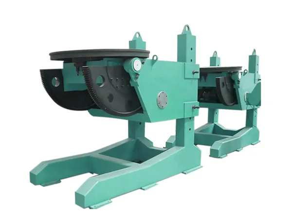
Tower welding rotators play a critical role in fabricating wind turbine towers, where precision and stability directly affect weld quality and worker safety. Among all components, the locking mechanism stands as the first line of defense against unintended rotation, load slippage, or catastrophic failure. Understanding how these locking systems function — and what distinguishes a reliable design from a risky one — is essential for any operation that values both productivity and personnel protection. This article examines the engineering principles behind locking mechanisms in tower welding rotators, highlights key design variations, and explains why BOTA prioritizes safety in every rotator it produces.

Why Locking Mechanisms Are the Safety Core of Tower Welding Rotators

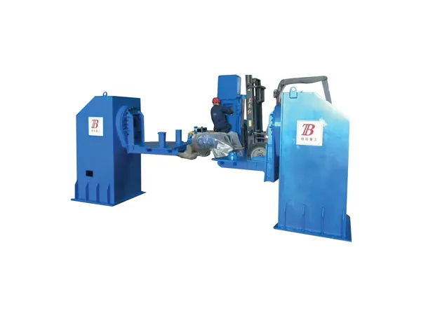
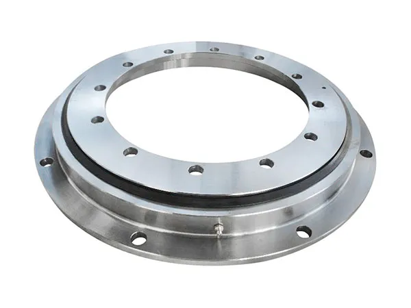
A tower welding rotator supports and rotates heavy cylindrical sections — sometimes weighing dozens of tons — during circumferential welding. The locking mechanism serves two distinct purposes: positional locking holds the workpiece stationary at a precise angle for manual or automated welding, while emergency braking stops rotation instantly if power fails or a hazard occurs. Without a robust locking system, a sudden shift in load could crush workers, damage the weld joint, or cause the entire assembly to topple. Industry standards such as ASME B30.7 and OSHA regulations require rotators to have redundant braking and locking features. BOTA integrates both active and passive locking elements to meet these strict requirements.

Common Locking Mechanism Types and How They Work

Three primary locking technologies dominate the market: friction-based, mechanical pawl, and electro-mechanical brakes. Each has distinct advantages and limitations.

  • Friction-based locking: Uses high-friction pads or discs pressed against the rotation drum. Simple and cost-effective but prone to wear and reduced holding force under thermal expansion. Suitable for light-duty applications.
  • Mechanical pawl and ratchet: A spring-loaded pawl engages a toothed wheel, providing positive mechanical lock. Excellent for static holding but cannot be engaged while the rotator is moving — requiring precise alignment before locking.
  • Electro-mechanical brakes (spring-applied, power-released): The industry gold standard. In normal operation, electromagnetic force releases the brake; upon power loss or emergency stop, springs push brake pads against a steel disc, stopping rotation within milliseconds. These brakes offer failsafe operation and consistent torque, even after repeated cycles.

BOTA’s tower welding rotators exclusively use spring-applied, power-released electro-mechanical brakes on the main drive shaft, supplemented by a secondary mechanical locking pin for maintenance and setup positions. This dual-layer approach ensures that even the primary brake’s electrical system fails, the mechanical pin prevents dangerous drift.

BOTA’s Locking Mechanism Advantages: A Side-by-Side Comparison

When evaluating rotator suppliers, the differences in locking design directly impact safety margins, maintenance intervals, and total cost of ownership. The table below compares BOTA’s standard locking system with conventional friction-only designs.

For more information about the locking mechanism of the safety-first tower welding rotator, please click to visit:https://www.bota-weld.com/en/a/news/locking-mechanisms-s.html

Boost Throughput: 4-Axis Wind Tower Welding Rotator Features

In the demanding field of wind tower manufacturing, welding efficiency directly impacts project timelines and profitability. Traditional rotators often struggle to handle the large, cylindrical sections of wind towers with the precision and speed required for modern production lines. The BOTA 4-axis wind tower welding rotator addresses these challenges by integrating advanced motion control and robust construction, enabling fabricators to significantly increase throughput without compromising weld quality. This article examines the specific features that make this system a game-changer for wind tower welding operations.

1. 4-Axis Design: The Foundation of Enhanced Throughput

Unlike standard 2-axis or 3-axis rotators, the BOTA 4-axis system provides independent rotational control for both the headstock and tailstock, plus two additional axes for tilting or lateral positioning. This configuration allows the welding torch or workpiece to be maneuvered into optimal positions without manual re-clamping, reducing cycle times. The synchronized motion of all four axes enables continuous welding of complex circumferential and longitudinal seams, eliminating interruptions caused by manual repositioning. This is particularly valuable for wind tower sections that require multiple weld passes with precise weave patterns.

2. Key Features That Drive Productivity

wind tower welding rotator

Independent Variable-Speed Drives

Each axis is powered by a dedicated servo motor with independent speed control, allowing fine adjustments from 0.01 to 10 RPM. This ensures consistent weld travel speed across varying diameters and wall thicknesses, reducing the need for operator intervention and post-weld grinding.

For more information on the characteristics of four-axis wind turbine welding rotary units that improve throughput, please click to visit:https://www.bota-weld.com/en/a/news/4-axis-welding-rotator-features.html

Precision Welding Positioner for Wind Tower Sections Up to 8m Diameter

Fabricating wind turbine towers requires welding massive steel sections that can reach 8 meters in diameter and weigh dozens of tons. Achieving consistent weld quality on such large components demands more than a standard positioner—it requires a precision welding positioner engineered for extreme loads, precise rotation control, and seamless integration into automated production lines. This article examines the key factors that make a positioner suitable for wind tower sections up to 8m diameter and explains why BOTA’s solutions deliver the reliability and performance that fabricators need to meet rising quality standards.

The Critical Role of Precision Welding Positioners in Wind Tower Fabrication

Why 8m Diameter Sections Require Specialized Equipment

Wind tower sections are not only large but also demand tight tolerances to ensure proper alignment during field assembly. A positioner for 8m diameter sections must handle eccentric loads, maintain steady rotation speeds as low as 0.01 rpm, and provide indexing accuracy within fractions of a degree. Conventional two-wheel or standard roller-type positioners often cannot support the combined weight and diameter without risking instability or excessive wear.

Challenges of Welding Large-Scale Wind Tower Sections

Beyond size, the welding process itself introduces challenges: longitudinal seams on conical sections, circumferential welds joining multiple rings, and repair welds on high-strength steel plates. Each scenario requires the positioner to tilt or rotate the part to an optimal welding angle. BOTA’s positioners incorporate dual-axis rotation and variable-speed drives that allow operators to place every weld at the 1 o’clock or 2 o’clock position—the ideal orientation for achieving full penetration and minimal defects.

Key Features of BOTA Precision Welding Positioners

  • High load capacity: Models handle up to 60 tons with reinforced headstock/tailstock configurations, ensuring long-term rigidity.
  • Precision rotation control: Servo-driven, backlash-free gearboxes deliver angular repeatability within ±0.05°.
  • Modular design: Interchangeable clamping jaws and adjustable center heights accommodate both 6m and 8m diameter sections without retooling.
  • Safety interlocks: Redundant braking systems and overload protection meet international machinery safety standards.
  • Automation-ready: Standard Profinet or EtherCAT interface allows direct connection to robot controllers or welding power sources.

For more information on precision welding positioners suitable for wind tower sections with diameters up to 8 meters, please click to visit:https://www.bota-weld.com/en/a/news/positioner-wind-tower.html

Eliminate Manual Flipping: Automated Rotator for Tower Fabrication

Imagine a fabrication floor where workers no longer risk injury by manually flipping heavy tower sections, where cycle times shrink by half, and where every rotation is perfectly aligned for welding and coating. This is not a distant vision—it is the reality delivered by an automated rotator system. For manufacturers of transmission towers, wind turbine towers, and other large cylindrical structures, eliminating manual flipping is not just an operational upgrade; it is a strategic imperative. BOTA has engineered a solution that redefines workflow efficiency and worker safety, making cumbersome manual handling a relic of the past.

Challenges of Manual Flipping in Tower Fabrication

Traditional tower fabrication relies on overhead cranes and manual labor to rotate heavy steel sections—often weighing several tons—during welding, grinding, and coating processes. This method introduces multiple pain points:

  • Safety hazards: Workers must physically guide and stabilize unstable loads, leading to frequent near-misses and crush injuries.
  • Low productivity: Each flip requires crane setup, repositioning, and coordination among multiple workers; a single rotation can take 15–30 minutes.
  • Quality inconsistency: Manual positioning often results in misalignment, requiring rework and compromising weld integrity.
  • Workflow bottlenecks: The entire production line pauses during flipping operations, creating idle time for downstream processes.

These challenges drive up operational costs and limit throughput, especially as tower sizes grow to meet wind energy and infrastructure demands. A paradigm shift is needed—one that an automated rotator delivers.

How an Automated Rotator Transforms the Workflow

Welding Rotator

An automated rotator for tower fabrication is a robust, programmable system that grips, lifts, and rotates tower sections around a central axis with minimal human intervention. BOTA’s design integrates servo-driven rollers, hydraulic clamps, and a PLC-based control interface to enable seamless 360-degree positioning at variable speeds. Key operational improvements include:

Elimination of Crane Dependency

Once the tower section is loaded onto the rotator (often via a simple transfer cart), all subsequent rotations occur without overhead crane involvement. This frees up crane capacity for other critical tasks and eliminates the coordination delays associated with shared equipment.

For more information about automatic rotators for manufacturing towers that eliminate the need for manual inversion, please click here:https://www.bota-weld.com/en/a/news/automated-rotator-for-tower-fabrication.html

How to Choose a Wind Tower Welding Rotator for 100-Ton Sections

Selecting a welding rotator for 100-ton wind tower sections is a critical decision that directly impacts weld quality, production throughput, and operational safety. The extreme weight, large diameter, and stringent tolerance requirements of modern wind tower sections demand a rotator system engineered for stability, precise speed control, and long-term reliability. This guide walks through the essential parameters—load capacity distribution, rotation speed range, drive torque, and structural rigidity—so you can confidently specify a rotator that matches your sections and production goals. Throughout this guide, we reference proven configurations from BOTA, a manufacturer with extensive experience in heavy-section welding automation.

1. Understanding Your Section Parameters

Before evaluating rotator specifications, you must define the physical characteristics of the 100-ton sections you plan to rotate. Wind tower sections are typically tapered cylinders with diameters ranging from 2.5 m to 4.5 m and lengths between 10 m and 30 m. The section’s center of gravity (COG) is rarely at the geometric center—it shifts toward the heavier end due to varying wall thickness and flanges. A rotator must accommodate this off-center loading without excessive deflection or vibration. Key data points to collect: exact weight, overall length, end diameters, wall thickness variation, and flange weight. Calculate the eccentric load moment (mass × offset distance) to determine the minimum rotational torque required. BOTA recommends providing a 3D CAD model or a detailed dimensional drawing to their engineers for a precise rotator sizing analysis.

2. Core Technical Specifications of a 100-Ton Rotator

welding rotator

2.1 Load Capacity and Wheel Configuration

A rotator rated for 100 tons typically uses two driven wheels and two idler wheels, arranged in a longitudinal or cross-axis layout. Each wheel set must share the load evenly. For example, BOTA’s BWR-100T series uses heavy-duty forged steel wheels with a hardened tread surface to minimize flattening under sustained high loads. The wheel spacing should be adjustable to match the section’s diameter range. A gap of 200–400 mm between roller faces prevents flange interference. Check the wheel’s dynamic load rating—never operate a rotator at its static maximum during continuous welding.

For more information on how to select the right welding rotator for a 100-ton wind turbine, please click here:https://www.bota-weld.com/en/a/news/wind-tower-rotator-choose.html

Why Precision Slewing Bearings Matter for Wind Turbine Performance

In the competitive landscape of wind energy, every component must deliver maximum reliability and efficiency. Among these, the slewing bearing—a critical rotational joint connecting the nacelle to the tower, and the blades to the hub—directly influences turbine performance. However, not all slewing bearings are equal. Precision matters. A high-precision slewing bearing ensures smooth rotation, precise load distribution, and extended service life, while a generic or poorly manufactured bearing can lead to misalignment, increased friction, and premature failure. This article examines why precision slewing bearings are essential for wind turbine performance and how choosing the right partner—such as LYMC—can make a measurable difference in your fleet’s uptime and energy output.

The Critical Role of Slewing Bearings in Wind Turbines

Wind turbines rely on two primary slewing bearings: the yaw bearing (connecting the nacelle to the tower) and the pitch bearing (connecting each blade to the hub). These bearings allow the turbine to orient itself toward the wind and adjust blade angles for optimal power capture. Any deviation in rotation accuracy or load capacity can trigger a cascade of issues:

  • Yaw bearing: Must handle axial, radial, and moment loads while enabling precise 360-degree rotation. Inaccurate alignment increases yaw drive wear and reduces energy capture.
  • Pitch bearing: Endures dynamic loads from wind gusts and blade inertia. Poor precision leads to uneven blade angles, causing vibration, reduced aerodynamic efficiency, and structural stress.

High-precision bearings minimize internal clearance, reduce friction torque, and maintain consistent geometry over thousands of operational hours. This directly translates to lower parasitic losses, better power generation, and fewer service interventions.

Key Performance Impacts of Precision Slewing Bearings

1. Energy Efficiency and Power Output

A slewing bearing with excessive clearance or uneven raceway geometry increases rotational resistance. Studies show that friction losses in yaw and pitch bearings can account for up to 2-3% of total energy loss in a turbine. With precision bearings, friction torque is reduced by up to 30%, allowing the turbine to capture more energy from the same wind resource. For a 3 MW turbine operating 7.000 full-load hours per year, a 2% efficiency improvement yields an additional 420 MWh annually—equivalent to €30.000-40.000 in added revenue at current market prices.

For more information on the critical importance of precision slewing bearings to wind turbine performance, please click to visit:https://www.mcslewingbearings.com/a/news/precision-slewing-be.html

Slewing Bearing Load Capacity: What Every Engineer Should Know

For any engineer working with rotating machinery—whether in construction equipment, wind turbines, or industrial robotics—understanding slewing bearing load capacity is not just a technical detail; it is the foundation of reliable design. Selecting the wrong bearing or misjudging the applied loads can lead to premature failure, costly downtime, or even catastrophic structural failure. This article breaks down the three fundamental load components, the factors that influence capacity, and a practical selection framework. We will also highlight how LYMC, a trusted manufacturer of high-precision slewing bearings, engineers its products to meet demanding load requirements with proven performance.

Understanding the Three Types of Load on a Slewing Bearing

A slewing bearing must simultaneously support axial loads, radial loads, and tilting moments. Each type imposes different stress distributions on the raceways and rolling elements, and real-world applications rarely see pure loading—most involve combinations of all three.

Axial Load (Thrust Load)

Axial load acts parallel to the bearing’s axis of rotation. In a crane, for example, the weight of the boom and lifted load produces a downward axial force. Slewing bearings are generally strongest in the axial direction, but the magnitude and direction (upward vs. downward) must be considered. LYMC designs raceway profiles to maximize axial load distribution, reducing contact stress at the edge of the rollers.

Radial Load

Radial load acts perpendicular to the rotation axis. In horizontal applications such as indexing tables or excavator swing systems, radial forces from side loads or gear reactions can be significant. While slewing bearings are not optimized for pure radial loads, modern designs with crossed roller elements or four-point contact balls provide moderate radial capacity. Engineers must verify that the radial component does not exceed the bearing’s rating.

Tilting Moment (Moment Load)

The tilting moment is often the most critical load type for slewing bearings. It results from offset axial loads or lateral forces that create a torque about the bearing’s center. For example, a tower crane’s jib creates a large overturning moment that the slewing bearing must resist. Capacity against tilting moment is typically limited by raceway indentation and fatigue life. LYMC’s proprietary heat treatment and raceway grinding processes improve moment capacity by up to 15% compared to standard industry benchmarks.

Key Factors That Influence Load Capacity

Load capacity is not a fixed number; it depends on material properties, geometry, lubrication, and operating conditions. Understanding these factors helps engineers avoid over-specification (waste) or under-specification (risk).

For more information on the load-bearing capacity of slewing bearings that every engineer should know, please click here:https://www.mcslewingbearings.com/a/news/slewing-load-capacity.html

Maximize Crane Lifespan with Proper Slewing Bearing Maintenance

A crane is only as reliable as its slewing bearing. This critical component enables 360-degree rotation while supporting immense axial, radial, and tilting loads. Neglecting its maintenance can lead to catastrophic failures, costly downtime, and significantly shortened equipment life. However, with a structured maintenance regime, operators can dramatically extend crane lifespan and reduce total cost of ownership. This article outlines the essential practices for slewing bearing care, drawing on industry best practices and the specialized expertise of LYMC in heavy-duty rotating solutions.

The Critical Role of the Slewing Bearing in Crane Longevity

The slewing bearing acts as the mechanical pivot point between the crane’s upper structure and its undercarriage or foundation. It must withstand extreme forces while maintaining smooth, precise rotation. Over time, wear accumulates from friction, contamination, and micro-movements. Even minor degradation in the bearing’s raceways or rolling elements can amplify vibrations, increase drive motor loads, and accelerate fatigue in surrounding structures. Proper slewing bearing maintenance is therefore not optional—it is a direct determinant of the crane’s service life. Operators who treat the bearing as a consumable item without proactive care often face premature replacement costs that dwarf the investment in regular upkeep.

Common Causes of Slewing Bearing Failure

Understanding failure modes helps prioritize maintenance actions. The most frequent culprits include:

  • Inadequate lubrication: Insufficient grease or wrong type leads to metal-to-metal contact and rapid wear.
  • Contamination: Dirt, water, and abrasive particles enter through damaged seals, causing three-body abrasion.
  • Uneven loading: Repeated off-center loads or exceeding rated capacity induces local overstress and brinelling.
  • Corrosion: Moisture trapped in the bearing raceway initiates pitting and flaking.
  • Bolt loosening: Loss of preload in mounting bolts allows relative motion, fretting, and structural misalignment.

Each of these issues can be mitigated through systematic inspection and corrective action before irreversible damage occurs.

For more information on proper slewing bearing maintenance to maximize crane lifespan, please click here:https://www.mcslewingbearings.com/a/news/bearing-maintenance-.html

Top 5 Signs Your Slewing Bearing Needs Immediate Replacement

Slewing bearings are critical components in heavy machinery, from cranes and excavators to wind turbines and marine equipment. When they begin to fail, the consequences can be catastrophic: unplanned downtime, secondary damage, and even safety hazards. Recognizing the early warning signs of a failing slewing bearing can save your operation thousands of dollars in repairs and lost production. In this article, we outline the top five indicators that your slewing bearing needs immediate replacement — and what to do next to keep your equipment running safely.

1. Unusual Noise and Vibration During Operation

One of the most common early signs of slewing bearing degradation is abnormal noise or vibration. A healthy bearing operates with a smooth, consistent hum. If you hear grinding, clicking, or intermittent scraping sounds, it often indicates internal raceway damage, spalling, or contamination. Vibration that increases with load or rotation speed is equally concerning.

What Causes These Sounds?

  • Fatigue spalling on raceways or rolling elements
  • Brinelling from shock loads or improper mounting
  • Foreign debris entering the bearing cavity
  • Loss of lubrication film leading to metal-to-metal contact

Ignoring these auditory and tactile clues allows damage to propagate rapidly. Any sustained change in noise or vibration warrants immediate inspection. If the bearing is already showing visible wear, replacement with a high-quality unit from LYMC is the only reliable solution.

2. Excessive Clearance or Backlash

Slewing bearings are designed with precise internal clearance to accommodate thermal expansion and load deflection. Over time, wear on the raceways and rolling elements increases this clearance, resulting in backlash — a noticeable play between the turntable and the base structure. In excavators and cranes, this manifests as a delayed or loose response when the upper structure rotates.

For more information on the five signs that a slewing bearing needs immediate replacement, please click here:https://www.mcslewingbearings.com/a/news/slewing-bearing-signs.html

Slewing Bearing vs Traditional Bearing: Key Differences Explained

When selecting the right bearing for your rotating machinery, the choice often comes down to a slewing bearing versus a traditional bearing. Both serve the fundamental purpose of enabling rotational motion while supporting loads, yet their design philosophies, application scopes, and performance characteristics differ significantly. Understanding these differences is critical for engineers and procurement professionals who need to optimize equipment reliability, cost efficiency, and operational longevity. This article provides a rigorous, side-by-side comparison to help you determine which bearing type best suits your specific requirements. We will also highlight insights from LYMC, a manufacturer with extensive experience in both domains.

1. Fundamental Design and Structure Differences

The most apparent distinction between slewing bearings and traditional bearings lies in their physical architecture and how they handle forces. Traditional bearings—such as ball, roller, or tapered roller bearings—are typically compact, standardized components designed for high-speed rotation with moderate radial and axial loads. In contrast, slewing bearings (also known as slewing rings) are large-diameter, integrated assemblies that can simultaneously sustain heavy axial loads, radial loads, and tilting moments.

Load Capacity and Direction

Slewing bearings excel in applications where the load is not purely radial or axial but involves combined forces and overturning moments. Their design often incorporates multiple raceways with rows of balls or rollers (e.g., four-point contact ball or crossed roller) to capture forces from multiple directions. Traditional bearings, on the other hand, are optimized for uni‑directional or bi‑directional loading (e.g., deep‑groove ball bearings for radial loads, thrust bearings for axial loads). When tilting moments are present, traditional bearings may require complex mounting arrangements or multiple bearings in a back‑to‑back configuration, increasing system complexity.

Installation Complexity

Traditional bearings are generally off‑the‑shelf components that can be mounted using standard shaft and housing fits. Installation is relatively straightforward, often requiring only press‑fitting or heat‑fit methods. Slewing bearings, however, are bolted directly to adjacent structures (e.g., a turntable and a base) using a ring of mounting holes. This demands precise alignment and torque control, but it eliminates the need for additional housings or shafts. LYMC’s application engineers note that while slewing bearing installation is more involved, it simplifies the overall system design in heavy‑duty rotary applications such as cranes, excavators, and wind turbines.

2. Performance and Application Comparison

The following list summarizes key performance criteria where slewing bearings and traditional bearings diverge:

  • Speed capability: Traditional bearings operate at high RPM (thousands of revolutions per minute). Slewing bearings are designed for slow to moderate rotation (typically under 100 RPM).

For more detailed information on the main differences between slewing bearings and traditional bearings, please click to visit:https://www.mcslewingbearings.com/a/news/slewing-bearing-vs-traditional-bearing.html