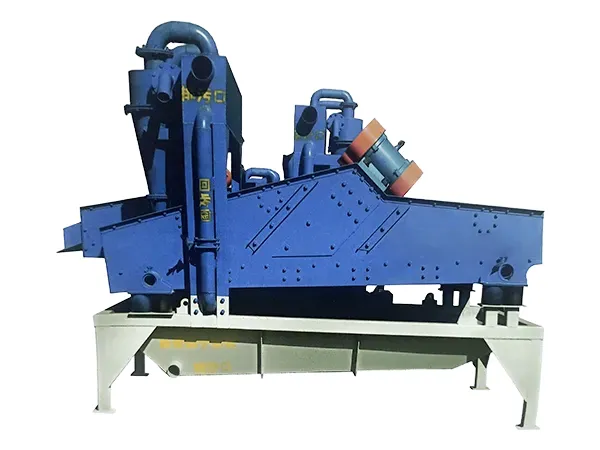
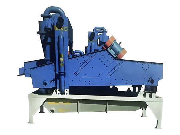
What should I do if the vibrating screen exciter is overheated?

The vibrating screen exciter is a critical component responsible for generating the vibration necessary for material screening. However, during prolonged or heavy-duty operation, the exciter may experience overheating—a common yet serious issue that can affect equipment performance, reduce operational lifespan, and lead to unexpected downtime.

Exciter overheating typically results from factors such as insufficient lubrication, excessive load, bearing failure, or poor maintenance practices. Identifying the root causes and implementing preventive measures are essential to ensure the stable and efficient functioning of vibrating screens in industrial settings. An overheated vibrating screen exciter (also called a vibrator motor or shaker mechanism) is a serious issue that needs immediate attention to prevent catastrophic failure and costly repairs.

Vibrating screen exciter overheating

vibrating screen exciter

1. IMMEDIATE ACTION: Safety First!

STOP THE SCREEN IMMEDIATELY: Do not continue running the screen. Continued operation will likely cause severe damage to bearings, seals, and potentially the entire exciter unit or screen structure.

FOLLOW LOCKOUT/TAGOUT (LOTO) PROCEDURES: Before attempting any inspection or maintenance, ensure the machine is completely de-energized and cannot be accidentally restarted. This is critical for your safety.

ALLOW IT TO COOL DOWN: Let the exciter cool down naturally. Do not try to force cool it with water or compressed air, as this can cause thermal shock and crack components.

2. TROUBLESHOOTING (Once Cool & Safe):

Once the unit has cooled down and LOTO procedures are in place, investigate the potential causes:

Check Lubrication (Most Common Cause):

Level: Is the oil level correct (check sight glass or dipstick)? Is the grease level correct (if grease lubricated)? Both too low (starvation) and too high (churning) can cause overheating.

Type: Are you using the correct type and viscosity of oil or grease specified by the screen and/or exciter manufacturer? Using the wrong lubricant is a major cause of overheating and failure.

Condition: Check the lubricant’s condition. Is it dark, sludgy, milky (water contamination), or does it smell burnt? This indicates degradation or contamination. Consider taking an oil sample for analysis if possible.

Frequency: When was it last lubricated? Was it according to the manufacturer’s recommended schedule?

Inspect Bearings:

Overheating is often a primary symptom of failing bearings. Listen for unusual noises (grinding, rumbling) when the machine was running (if you noticed any) or try carefully rotating the shaft by hand (if possible and safe) to feel for roughness or binding.

Check the bearing housing temperature regularly (using an infrared thermometer) during normal operation as part of preventative maintenance. Compare readings to baseline or manufacturer specs.

Check for Obstructions & Cleanliness:

Is the exciter housing covered in dirt, dust, or built-up material? This can act as an insulator, preventing proper heat dissipation. Clean the exterior thoroughly.

Ensure ventilation openings (if any) are clear.

Check Alignment & Mounting:

Are the exciter mounting bolts tight? Loose bolts can cause misalignment and stress.

If driven by an external motor via belts or a cardan shaft, check the alignment between the motor and the exciter. Misalignment puts excessive load on bearings.

Check Drive System (if applicable):

Belts: Are the drive belts tensioned correctly? Too tight puts excessive load on bearings; too loose can cause slippage and heat. Are the belts worn or damaged?

Sheaves/Pulleys: Are the sheaves worn or damaged? Are they aligned correctly?

For more detailed information on how to deal with overheating of the vibrating screen exciter, please click here: https://www.zexciter.com/en/a/news/vibrating-screen-exciter-overheating.html

Vibrating Screen Exciter Installation Guide

The vibrating screen exciter is a crucial component in screening equipment, responsible for generating the vibratory motion that enables material separation. Proper installation of the exciter is essential for ensuring the optimal performance, longevity, and safety of vibrating screens.

This guide provides step-by-step instructions for the correct installation of various types of screen exciters, covering preparation, alignment, fastening, lubrication, and initial testing. Whether for new equipment setup or replacement of existing exciters, following these guidelines will help reduce downtime and prevent premature wear or mechanical failure.

Vibrating Screen Exciter Installation Guide

vibrating screen exciter

Pre-Installation Preparation

Verify Parts:

Confirm you have the correct exciter model and configuration (rotation, mounting type) for the specific screen and position.】

Inspect the exciter for any shipping damage. Report any damage immediately.

Ensure you have the correct quantity, size, grade (typically Grade 8 or Metric 10.9), and length of new mounting bolts, hardened washers, and nuts (if applicable). Never reuse old mounting bolts.

Check if seals, O-rings, or gaskets are required and supplied.

Gather Tools & Equipment:

Calibrated Torque Wrench (appropriately sized for required torque values)

Socket Set and Wrenches (correct sizes for mounting bolts)

Lifting Equipment (crane, hoist, slings, shackles)

Alignment Tools (straight edge, dial indicators, laser alignment tool if connecting drive shafts)

Cleaning Supplies (wire brushes, scrapers, rags, solvent)

Pry Bars (use cautiously)

Anti-Seize Compound (check manufacturer recommendation)

Thread Locking Compound (check manufacturer recommendation, e.g., Loctite)

Lubricant (correct type and grade of oil or grease as specified by the manufacturer)

Measuring Tools (tape measure, feeler gauges)

Manufacturer’s Installation Manual and Screen Drawings

Prepare the Screen:

Thoroughly clean the exciter mounting surface(s) on the screen side box or exciter support beam. Remove all old gasket material, sealant, rust, dirt, grease, and paint. The surface must be clean, dry, and flat.

Inspect the mounting surface for flatness, cracks, or damage. Repair as necessary according to manufacturer specifications.

Clean out the bolt holes. Ensure threads (if tapped) are clean and undamaged. Chase threads with a tap if necessary, but do not remove significant material.

Prepare the Exciter:

Clean the mounting flange(s) of the new exciter.

Verify the correct orientation for installation (e.g., oil level plugs, breathers, rotation direction).

More detailed information about the installation guide of the vibrating screen exciter can be found at: https://www.zexciter.com/en/a/news/vibrating-screen-exciter-installation-guide.html

What are the maintenance tips for vibrating screens?

Vibrating screens play a vital role in many industries, including mining, construction, metallurgy, and recycling. These machines ensure efficient material separation and improve productivity. However, like any heavy-duty equipment, vibrating screens require regular maintenance to operate at peak performance and avoid unexpected breakdowns. Proper maintenance not only extends the machine’s lifespan but also ensures safety and minimizes downtime. In this guide, we’ll share practical vibrating screen maintenance tips to help you keep your equipment running smoothly and efficiently.Maintaining vibrating screens effectively is crucial for ensuring optimal performance, maximizing lifespan, and preventing costly downtime.

Vibrating Screen Maintenance Tips

Vibrating screens

I. Daily / Per Shift Checks (Visual & Auditory):

Listen for Abnormal Noises: Pay attention to any unusual grinding, knocking, rattling, or high-pitched sounds coming from the bearings, motor, or structure.

Observe Vibration: Check for smooth, consistent vibration across the entire screen deck. Look for erratic movement, shaking, or excessive bouncing, which could indicate imbalance, broken springs, or structural issues.

Check Material Flow: Ensure material is feeding evenly onto the screen and discharging properly. Look for build-up on side plates, feed boxes, or discharge lips.

Check for blinding (screen openings clogged) or pegging (near-size particles stuck).

Visual Scan for Obvious Damage: Quickly look for loose bolts, cracked welds (especially near high-stress areas), obvious holes or tears in the screen media, and damaged spray nozzles (if applicable).

Check Surrounding Area: Look for excessive spillage or dust, which might indicate worn seals or enclosure issues. Ensure walkways and access points are clear.

II. Weekly / Regular Inspections (More Detailed):

Screen Media Inspection (Crucial!):

Tension: Ensure screen panels (especially wire mesh) are properly tensioned. Loose screens wear out quickly, perform poorly, and can damage the screen box.

Check tensioning bolts/clamps.

Wear & Damage: Inspect for broken wires, tears, holes, excessive wear, or deformation in wire mesh, polyurethane, or rubber panels. Note wear patterns – uneven wear might indicate feed issues.

Blinding/Pegging: Check closely for clogged openings. If persistent, investigate the cause (moisture, particle shape, wrong opening size).

Clamping System: Inspect clamp bars, J-bolts, wedges, and associated hardware for wear, damage, or looseness. Ensure they are securing the media effectively.

Vibrator / Exciter Mechanism:

Bearing Temperature: Safely check bearing housing temperatures (using an IR temp gun is ideal). Compare readings over time and between bearings. A significant increase indicates potential problems.

Lubrication Levels (Oil): Check sight glasses for correct oil levels. Look for leaks around seals.

Grease Points: Check for signs of fresh grease purging (if grease lubricated) indicating proper lubrication. Clean excess old grease.

Mounting Bolts: Verify that the bolts securing the vibrator mechanism to the screen box are tight.

Drive System:

V-Belts: Check tension (not too tight, not too loose), wear (cracks, glazing), and alignment. Misaligned belts wear quickly and waste energy.

Drive Motor: Listen for bearing noise. Check mounting bolts. Ensure cooling fins are relatively clean.

Guards: Ensure all drive guards are securely in place.

Support Structure & Springs:

Springs (Coil or Rubber): Inspect for cracks, breakage, sagging, or deformation. Ensure the screen is sitting level.

Support Structure: Perform a more thorough check for cracks in welds or structural members, especially around spring mounts and support points. Check mounting bolts securing the screen to the structure.

Fasteners: Check the tightness of key bolts, particularly those holding the screen media, vibrator mechanism, side plates, and support structure connections. Use torque wrenches where specified.

III. Scheduled Preventive Maintenance (Monthly/Quarterly/Annually – Follow Manufacturer’s Recommendations):

Vibrating screens

Lubrication (Vital!):

Follow the Manual: Adhere strictly to the manufacturer’s specifications for lubricant type (oil or grease), quantity, and frequency.

Greasing: Use the correct grease type. Do not over-grease bearings, as this can cause overheating. Purge old grease if recommended.

Oil Changes: Change oil at recommended intervals. Check for contaminants (water, metal particles) in the old oil.

For more detailed information on vibrating screen maintenance tips, please click here: https://www.zexciter.com/en/a/news/vibrating-screen-maintenance-tips.html

What are the advantages of the welding column boom in industrial manufacturing?

The welding column and boom, also known as a welding manipulator, offers numerous advantages in industrial manufacturing, significantly enhancing efficiency, safety, and weld quality.

Welding column boom advantages for industrial manufacturing applications

welding column and boom

Improved Productivity and Efficiency:

Increased Deposition Rates: Automated or semi-automated welding processes facilitated by the column and boom allow for faster application of weld material.

Reduced Labor Costs: By automating welding tasks, the need for manual welders is reduced, leading to significant cost savings.

Faster Welding Speeds: Consistent and controlled movement of the welding head enables faster welding compared to manual methods.

Continuous Operation: These systems are designed for uninterrupted production, especially in shift-based operations.

Reduced Material Handling: For large workpieces, the manipulator can access various welding points without the need to reposition the material frequently.

Optimal Positioning: The boom and column allow for precise positioning of the welding head, ensuring the correct angle and distance for optimal weld quality and speed.

Enhanced Weld Quality:

Consistent Weld Quality: Automated movement and precise control lead to uniform and repeatable welds, minimizing defects.

Improved Accuracy: The system allows for accurate alignment of the welding torch with the weld seam, even in difficult-to-reach areas.

Ability to Perform Complex Welds: Column and boom systems can handle longitudinal, circumferential, and other complex welding tasks with greater precision than manual welding.

Increased Safety:

Reduced Welder Fatigue: Automating repetitive or physically demanding welding tasks reduces strain and fatigue on welders.

Access to Hazardous Areas: The manipulator can perform welding in areas that may be dangerous or difficult for human welders to access.

Safer Operation: Keeping welders away from the immediate welding arc and potential hazards improves overall workplace safety.

Organized Work Environment: Integrated cable channels help manage welding equipment and reduce tripping hazards.

welding column and boom

Greater Flexibility and Versatility:

Adaptability to Various Workpieces: Column and boom systems can handle a wide range of workpiece sizes, shapes, and configurations, including large, heavy, and complex parts.

Multiple Welding Processes: These systems can be integrated with various welding processes such as TIG, MIG/MAG, SAW, and plasma arc welding.

Extended Reach and Accessibility: The extendable and maneuverable boom allows access to different heights and welding positions.

For more detailed information about the advantages of welding column boom in industrial manufacturing, please click to visit: https://www.bota-weld.com/en/a/news/welding-column-boom-advantages-for-industrial-manufacturing-applications.html

How to improve the efficiency of welding manipulator

Improving the efficiency of a welding manipulator (often a robotic arm or a dedicated positioner used in automated or semi-automated welding) involves optimizing various aspects of the system and process.

How to improve the efficiency of welding manipulator

welding manipulator

Programming and Path Optimization:

Minimize Air Time: Reduce the time the manipulator spends moving between welds (“air cutting”). Optimize the path planning to take the shortest, fastest routes between weld points.

Optimize Motion Speeds: Use the highest safe and repeatable speeds for non-welding movements. Tune acceleration and deceleration parameters.

Weld Sequence Optimization: Plan the order of welds to minimize overall manipulator travel, reduce heat distortion (which can necessitate rework or slower welding later), and maintain optimal torch angles.

Offline Programming (OLP): Use OLP software to create, simulate, and optimize programs without stopping the production line. This maximizes manipulator uptime.

Use Appropriate Motion Types: Employ linear movements (L) for welding paths and joint movements (J) for faster transitions between distant points where path accuracy isn’t critical.

Welding Process Optimization:

Optimize Weld Parameters: Fine-tune voltage, wire feed speed (amperage), travel speed, and gas flow for maximum deposition rate and minimal spatter/defects, reducing post-weld cleaning and rework.

Select Efficient Welding Processes: Consider advanced processes like pulsed MIG/MAG, CMT (Cold Metal Transfer), or high-speed TIG variants if applicable, as they can offer higher speeds, lower heat input, or reduced spatter.

Improve Torch Angle and Stick-out: Ensure the torch angle and contact-tip-to-work distance (stick-out) are optimized and consistently maintained for stable arc and good penetration.

Fixturing and Part Presentation:

Design for Automation (DFA): If possible, influence part design to improve accessibility for the manipulator and simplify weld joints.

High-Quality, Repeatable Fixtures: Use fixtures that locate parts accurately and consistently every time. Poor fit-up is a major cause of inefficiency and weld defects.

Quick Changeovers: Design or utilize fixtures that allow for fast loading and unloading of parts. Consider indexing tables or dual fixture setups where one side can be loaded/unloaded while the other is being welded.

Optimize Fixture Access: Ensure the fixture provides clear access for the manipulator arm and welding torch without collisions.

welding manipulator

Sensing and Adaptive Control:

Touch Sensing: Use the welding wire or a probe to accurately locate the start of weld joints, compensating for minor part variations.

Through-Arc Seam Tracking (TAST): For suitable joints, use TAST to allow the robot to follow the weld seam automatically, compensating for variations during welding.

For more detailed information on how to improve the efficiency of welding operators, please click here: https://www.bota-weld.com/en/a/news/improvement-of-welding-manipulator-work-efficiency.html

What are the maintenance tips for welding positioner

Proper maintenance of a welding positioner is crucial for ensuring its longevity, accuracy, safety, and reliable performance. Neglecting maintenance can lead to breakdowns, inaccurate positioning, potential safety hazards, and costly repairs.

Welding positioner maintenance

welding positioner

1. Follow the Manufacturer’s Manual:

This is the most important tip. Always refer to the specific operation and maintenance manual provided by the positioner’s manufacturer. It will detail specific lubrication points, lubricant types, inspection schedules, and procedures tailored to your model.

2. Regular Cleaning:

Daily/Shiftly: Wipe down the positioner, especially the turntable/faceplate, control panel, and visible moving parts.

Remove Weld Spatter: Spatter can interfere with grounding, damage surfaces, clog T-slots, and hinder smooth operation. Use appropriate tools (spatter scrapers, wire brushes) carefully to avoid damaging surfaces.

Keep Electrical Cabinets Clean: Periodically (as recommended, and with power LOCKED OUT), check for dust buildup inside control cabinets, which can cause overheating or short circuits. Use compressed air or a vacuum carefully.

3. Lubrication:

Adhere to Schedule: Follow the manufacturer’s lubrication schedule religiously. This often includes lubricating gearbox(es), bearings, tilt mechanisms (like screw jacks or hydraulic cylinders), and rotation drives.

Use Correct Lubricants: Always use the type and grade of oil or grease specified by the manufacturer. Using the wrong lubricant can cause damage or premature wear.

Check Fluid Levels: Regularly check oil levels in gearboxes and hydraulic reservoirs (if applicable). Top up as needed.

Grease Fittings: Clean grease fittings (zerks) before applying grease to prevent injecting contaminants. Apply grease until fresh grease begins to emerge (or as specified). Wipe off excess grease.

welding positioner

4. Mechanical Inspections:

Fasteners: Regularly check critical bolts and fasteners for tightness, including:

Mounting bolts securing the positioner to the floor.

Bolts securing the turntable/faceplate.

Motor and gearbox mounting bolts.

Turntable/Faceplate: Inspect for flatness, damage, and wear. Ensure T-slots or chuck mounting points are clean and undamaged.

For more detailed information on welding positioner maintenance tips, please click here: https://www.bota-weld.com/en/a/news/welding-positioner-maintenance.html

What are the types of welding rotators?

Welding rotators, also known as turning rolls or tank rollers, are essential equipment in the automatic welding of cylindrical workpieces such as tanks, pipes, pressure vessels, and wind towers. Depending on the workpiece size, weight, material, and welding requirements, different types of welding rotators are available on the market. This guide introduces the most common types of welding rotators and their main features.Their primary purpose is to rotate cylindrical workpieces like pipes, tanks, and pressure vessels, allowing welders to maintain a consistent, often downhand, welding position for better quality, efficiency, and safety.

Welding Rotators Types

Welding rotators

Conventional (or Standard) Turning Rolls:

Description: These consist of a powered drive unit and one or more non-powered idler units. Each unit typically has two rollers. The distance between the rollers on each unit is manually adjustable (often via bolts in slots or a leadscrew) to accommodate different workpiece diameters.

How they work: You manually set the roller spacing on both the drive and idler units to match the diameter of the workpiece you intend to weld. The workpiece then rests on these rollers.

Pros: Generally simpler in design, often more cost-effective for a given capacity, robust.

Cons: Requires manual adjustment time when changing workpiece diameters, workpiece needs careful centering, the centerline height of the workpiece may change slightly depending on the diameter and roller setting.

Best Suited For: Shops that frequently work with similar-sized workpieces or where setup time for diameter changes is less critical.

Self-Aligning Rotators (SAR):

Description: These also consist of a drive unit and idler unit(s). However, the key difference is that the roller brackets are designed to pivot or adjust automatically.

As the workpiece is lowered onto the rotator, the rollers swing open or closed to conform to the workpiece’s diameter without manual adjustment of roller spacing.

How they work: The pivoting mechanism ensures that the rollers automatically cradle the workpiece, maintaining multiple contact points. This design often keeps the centerline height of the workpiece relatively constant across a wide range of diameters.

Pros: Significantly faster setup when changing between different workpiece diameters, automatically centers the workpiece to some extent, provides better support (especially for thin-walled vessels) by distributing the load over more contact points, reduces the risk of workpiece marking.

Cons: More complex mechanism, generally more expensive than conventional rotators of the same capacity.

Best Suited For: Fabrication shops dealing with a wide variety of workpiece diameters, applications where quick changeover is important, handling large or thin-walled vessels where good support is crucial.

Other Considerations & Variations (Features often found on both types):

Welding rotators

Drive Unit vs. Idler Unit: Rotator sets always include at least one powered “Drive Unit” that provides the rotation and one or more unpowered “Idler Units” that simply support the workpiece. You can add more idler units for longer vessels.

Capacity: Rotators are rated by their weight capacity (e.g., 1 ton, 5 tons, 50 tons, 100+ tons) and the diameter range they can handle.

More detailed information about welding rotator types can be found at: https://www.bota-weld.com/en/a/news/welding-rotators-types.html

How to calibrate HPGR roll gap settings

Calibrating the roll gap on a high-pressure grinding roll (HPGR) is a critical maintenance task for ensuring optimal performance, energy efficiency, and preventing damage. Here’s a comprehensive guide on how to do it.

Why Calibrate the Roll Gap?

high-pressure grinding roll

Performance: The gap directly influences the pressure applied to the material, affecting particle size reduction, throughput, and product quality.

Energy Efficiency: An incorrect gap (too wide or too narrow) leads to inefficient energy use.

Wear Management: Maintaining the correct gap and ensuring parallelism prevents uneven wear on the roll surfaces (tires/segments) and potential contact between the rolls, which can cause catastrophic damage.

Machine Protection: Ensures the hydraulic system operates within its design parameters and protects bearings and frame components from excessive stress.

Key Concepts:

Roll Gap (S): The minimum distance between the surfaces of the two counter-rotating rolls (one fixed, one floating/movable).

Operating Gap: The actual gap during operation under pressure, which might differ slightly from the static (no-load) gap due to system flex. Calibration typically refers to setting the static gap.

Parallelism: Ensuring the gap is consistent across the entire width of the rolls. Non-parallelism leads to uneven grinding, skewed wear, and potential machine stress.

Common Calibration Methods:

Feeler Gauges (Most Common for Static Gap): Using precise metal strips of known thickness.

Lead Wire / Soft Metal Slugs: Compressing a soft material between the rolls and measuring its deformed thickness.

Mechanical Jigs/Templates: Using specialized tools provided by the OEM.

Electronic Measurement (Control System Reference): Some systems use sensors or a “roll touch” procedure as a zero reference, then apply an offset. This still requires physical verification.

How to calibrate HPGR roll gap settings

high-pressure grinding roll

Step-by-Step Calibration Procedure (General Guide – ALWAYS Prioritize Your OEM Manual):

Phase 1: Preparation & Safety

SAFETY FIRST – Lockout/Tagout (LOTO): Absolutely critical. Isolate ALL energy sources (electrical, hydraulic, pneumatic) to the HPGR according to established site procedures before any work begins. Ensure the machine cannot be started accidentally.

Consult the OEM Manual: This is your primary resource. Procedures can vary significantly between manufacturers and models.

Gather Tools:

More detailed information on how to calibrate the HPGR roll gap setting can be found at: https://www.zymining.com/en/a/news/hpgr-roll-gap-calibration-setting.html

How to Operate a Briquetting Machine: Step-by-Step Guide

Operating a briquetting machine involves several key steps to ensure efficient and safe production of briquettes. Here’s a general step-by-step guide. Keep in mind that specific procedures might vary slightly depending on the type and model of your briquette machine, so always consult the manufacturer’s manual for detailed instructions.

How to Operate a Briquetting Machine

briquetting machine

1. Preparation and Checks

Raw Material Preparation: Ensure your raw material (e.g., sawdust, agricultural waste) is of the correct size and moisture content as specified by your machine’s requirements (often below 15%). You may need to use a crusher or a dryer to achieve this.

Machine Inspection: Before starting, thoroughly inspect the briquette machine for any loose bolts, worn parts, or obstructions. Pay close attention to the screw propeller, forming die, and heating elements.

Lubrication: Check and lubricate all necessary parts as indicated in the machine’s manual. Proper lubrication is crucial for smooth operation and longevity.

Cooling System (if applicable): If your machine has a cooling system (often water-based), ensure it is properly connected and filled.

Electrical Connections: Verify that the machine is correctly connected to a stable power supply with the correct voltage. Ensure all wiring is secure and the machine is properly grounded.

Safety Checks: Make sure all safety guards and emergency stop buttons are in place and functioning correctly. Ensure the work area is clear of any obstructions and that a fire extinguisher (powder, foam, or CO2) is readily accessible. Operators should wear appropriate personal protective equipment (PPE) such as respirator masks.

2. Machine Start-Up

Main Switch: Turn on the main power switch of the machine.

Heating System: If your machine uses heat to soften the lignin in the raw material, turn on the heating system and set the temperature to the required level (typically between 120-300°C depending on the material). Allow sufficient time for the machine to reach the set temperature.

No-Load Running: Once the machine reaches the operating temperature (if applicable), run it without any raw material for a few minutes (around 3-30 minutes as per some recommendations). Listen for any unusual noises or vibrations. If any abnormalities occur, stop the machine immediately and identify the issue.

3. Briquette Production

Material Feeding: Gradually start feeding the prepared raw material into the hopper. Begin with a small amount and slowly increase the feeding rate until briquettes are formed consistently and are of good quality. Avoid overfeeding, which can cause blockages.

Monitoring Briquette Quality: Continuously monitor the quality of the produced briquettes. Check for density, shape, cracks, and surface finish. Adjust the feeding rate, temperature (if applicable), and pressure as needed to maintain optimal quality.

Temperature Regulation: Maintain the set temperature of the heating elements to ensure proper briquetting. Fluctuations in temperature can affect the quality of the briquettes.

Discharge Area: Ensure the briquettes are discharged smoothly and there is adequate space for them to accumulate or be conveyed away. Some suggest directing the output towards a wall with a plank in front initially.

briquetting machine

4. Machine Shut-Down

Stop Feeding: Gradually stop feeding raw material into the hopper.

Empty the Machine: Allow the machine to continue running until all the material inside the forming chamber and screw conveyor is expelled.

More detailed information about how to operate the briquetting machine can be found at: https://www.zymining.com/en/a/news/briquetting-machine-operation.html

HPGR Wear Protection Solutions

As HPGRs are required to handle extremely high pressures and abrasive materials, wear is a major operating cost and a factor in their efficiency and availability. Effective wear protection is essential. Let’s analyze wear protection solutions for high pressure grinding rolls (HPGR).

HPGR Wear Protection Solutions

HPGR

1. Roll Surface Materials & Design:

Base Material: The core roll body is typically made from high-strength forged steel or sometimes specialized cast iron alloys to withstand the immense operating pressures.

Wear Surface Design: The most common approaches for the actual wear surface are:

Solid Rolls (Less Common for Large Units): The entire roll body might be made of a wear-resistant alloy, but this is less common for large, modern HPGRs due to cost and manufacturing challenges.

Segmented Rolls: The roll surface is made of multiple cast or forged segments bolted or keyed onto the roll body. This allows for easier replacement of worn sections.

Tires/Sleeves: A replaceable outer wear layer (the “tire” or “sleeve”) is shrunk-fit or mechanically fastened onto a core roll shaft/body. This is a very common and practical design, allowing for easier replacement of the wear surface without replacing the entire roll body.

HPGR

2. Surface Protection Technologies (Applied to Tires/Sleeves or Segments):

This is where the most distinct wear protection strategies lie:

Welded Hardfacing Overlays:

Process: Applying layers of extremely hard, wear-resistant weld material onto the roll surface. Common methods include Submerged Arc Welding (SAW) or Open Arc Welding (Flux-Cored Arc Welding – FCAW).

Materials: Typically high-chromium carbide (CrC) alloys, complex carbides, or sometimes tungsten carbide (WC) composites within a matrix.

For more detailed information on HPGR wear protection solutions, please visit: https://www.zymining.com/en/a/news/hpgr-wear-protection-solutions.html