Avoid These Common Crossed Roller Bearing Mistakes

Crossed roller bearings are precision components that deliver exceptional rigidity and rotational accuracy in demanding applications such as robotics, medical equipment, and machine tool turrets. However, even the best engineered bearing will fail prematurely if common mistakes are made during selection, installation, lubrication, or maintenance. Understanding these pitfalls is essential for maximizing service life, avoiding costly downtime, and ensuring that your machinery operates at peak performance. This article highlights the most frequent crossed roller bearing errors and provides practical guidance to help you steer clear of them.

Mistake #1: Incorrect Bearing Selection for the Application

The foundation of reliable bearing performance starts with choosing the right bearing type and size. Many engineers underestimate the complexity of crossed roller bearings, which leads to suboptimal selection and eventual failure.

Ignoring Load Direction and Magnitude

Crossed roller bearings can handle combined axial, radial, and moment loads, but their capacity varies with the direction and distribution of the load. A common mistake is selecting a bearing based solely on radial load capacity without calculating the actual moment loads generated by cantilevered or offset masses. This oversight can result in premature fatigue or raceway brinelling. Always evaluate the full load spectrum, including shock loads, and consult the bearing manufacturer’s rating tables for the equivalent dynamic load under combined loading conditions.

Overlooking Rotational Accuracy Requirements

Applications like indexing tables and rotary encoders demand very tight runout and positioning accuracy. Selecting a standard crossed roller bearing when a higher accuracy class (such as P5 or P4) is required can lead to unacceptable error in the system. Conversely, overspecifying accuracy without need drives up cost. Match the bearing precision grade to the actual performance requirements of your equipment.

Mistake #2: Poor Mounting and Housing Fit
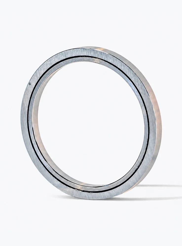
Even the most precise crossed roller bearing will perform poorly if it is installed in a housing or on a shaft with incorrect fits. Improper interference or clearance affects the internal clearance of the bearing, which in turn alters contact stress and can cause skidding or excessive heat.

Incorrect Tolerance of Mating Surfaces

Machining the housing bore or shaft to the wrong tolerance is one of the most common installation mistakes. If the fit is too tight, the crossed roller bearing’s internal clearance is reduced, leading to increased friction and heat generation. If the fit is too loose, the bearing can creep, causing wear on the housing and shaft, and eventually resulting in misalignment. Always follow the manufacturer’s recommended shaft and housing tolerances for the specific bearing series.

Using the Wrong Mounting Method

Crossed roller bearings are often split into two-piece or three-piece designs. Some installers attempt to press the entire bearing on the shaft using force that bypasses the rolling elements, which can damage the raceways. Instead, use the proper mounting sleeves or apply uniform pressure on the inner ring when mounting onto a shaft. For thin-wall bearings, avoid using direct hammering; use a suitable press or a hydraulic expansion tool to avoid distortion.

Mistake #3: Neglecting Proper Lubrication

Lubrication is the lifeline of any bearing, and crossed roller bearings are no exception. Incorrect lubrication or inadequate quantities are leading causes of premature bearing failure.

Using the Wrong Grease or Oil

Crossed roller bearings operate at various speeds, temperatures, and load conditions. Using a grease with insufficient viscosity or a base oil that is not compatible with the operating environment can lead to poor film formation and metal-to-metal contact. For high-speed applications, a low-viscosity oil circulating system may be required, while low-speed high-load applications benefit from high-viscosity grease with EP (extreme pressure) additives. Always consult the bearing manufacturer or a lubrication engineer to choose a lubricant that matches the specific operating conditions.

Over-Lubrication or Under-Lubrication

Too much grease can cause churning, which raises the temperature and degrades the lubricant. Too little grease leaves the bearing unprotected. Many lubrication schedules are based on general estimates rather than actual operating hours. Implement a defined preventive maintenance schedule that specifies the correct volume and interval for regreasing, based on the bearing’s operating time and environment. For sealed crossed roller bearings, the initial lubrication is often life-long, but only if the correct amount is pre-filled; do not attempt to regrease sealed units unless instructed.

Mistake #4: Improper Handling and Storage
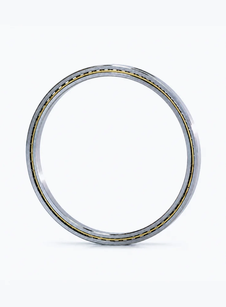
Crossed roller bearings are machined to tolerances of a few micrometers. Mishandling or poor storage can damage these components before they are ever installed.

Exposing Bearings to Contamination

Dust, moisture, and abrasive particles are the enemies of precision bearings. Leaving bearings unboxed on a dirty workbench, using contaminated tools, or failing to clean the surrounding area before installation can introduce particles that cause early wear. Always keep bearings in their original packaging until installation, and use clean, lint-free cloths and gloves when handling.

…

Click here for more detailed information on avoiding these common cross-roller bearing errors: https://www.bobibearing.com/a/bearing-knowledge/crossed-roller-mistakes.html
Why Crossed Roller Bearings Develop Noise and How to Fix It

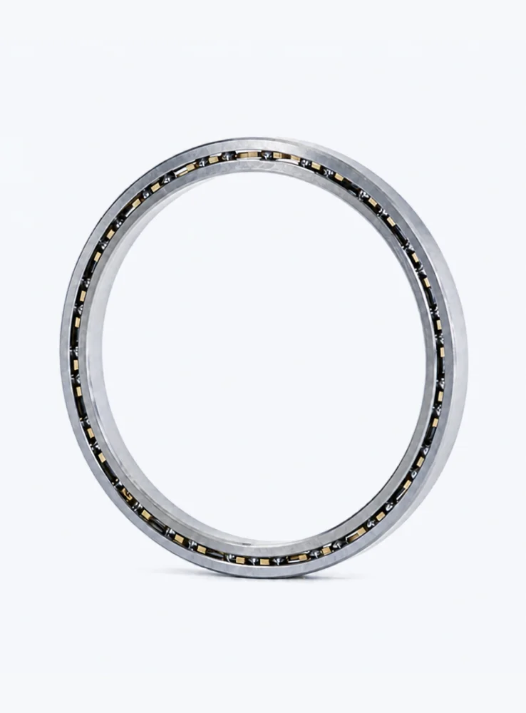
An unexpected noise from a crossed roller bearing is never a random event. In precision equipment such as indexing tables, robot axes, medical scanners, and semiconductor stages, a bearing that begins to grind, click, or squeal is sending an early warning that something has changed inside the mechanism. The sound is the audible symptom of a shift in contact conditions, surface quality, or lubrication state. If you can interpret the signal and respond quickly, you can avoid unplanned downtime and protect surrounding components from secondary damage. This article examines exactly why crossed roller bearings develop noise and provides a practical, step-by-step path to diagnose and correct the problem.

How Crossed Roller Bearings Work and Why Quiet Operation Matters

Crossed roller bearings use cylindrical rollers arranged perpendicularly to each other at 90 degrees, alternating between the inner and outer raceways in a single compact ring. This unique geometry allows the bearing to carry radial, axial, and moment loads simultaneously while delivering high rotational accuracy and rigidity.

Under normal operating conditions, these bearings are exceptionally quiet. The rolling elements move smoothly across the raceway with only a low, uniform hum at higher speeds. Any significant change in this acoustic baseline should be treated as a diagnostic event. In applications where positional accuracy is measured in microns, noise is rarely just a nuisance — it correlates with vibration, and vibration directly degrades accuracy.

Root Causes of Noise in Crossed Roller Bearings

Bearing noise can originate from multiple sources, and in many cases two or more factors act together. Understanding each root cause is the foundation of an effective fix.

1. Lubrication Failure or Incorrect Lubricant Selection

The most frequent cause of noise in crossed roller bearings is a breakdown in lubrication. Grease that has aged, dried, or been washed out loses its ability to form a full elastohydrodynamic film between rollers and raceways, resulting in metal-to-metal contact. The typical sound is a continuous, metallic whirring or scraping.

Conversely, using the wrong viscosity can create problems too. An over-packed bearing generates churning noise — a low, rumbling sound caused by the rolling elements struggling to push through excess grease. Proper grease volume in a crossed roller bearing is typically 30 to 35 percent of the free internal space, not fully packed.

2. Contamination and Foreign Particle Ingress

Even microscopic particles of dust, metal chips, or abrasive debris can enter the bearing through worn seals or during installation. Once inside, these particles act as grinding agents between the rollers and raceways, producing a harsh, scratchy noise that often increases with rotation speed. Hard particle contamination also accelerates raceway wear, which shortens service life dramatically.

…

Click here for more details on why crossed roller bearings generate noise and how to repair them: https://www.bobibearing.com/a/bearing-knowledge/crossed-noise-fix.html

Eliminating Play in Crossed Roller Bearing Systems

Crossed roller bearings are prized for their compact design and high stiffness, yet even the best-engineered systems can suffer from internal clearance, or play, that undermines positioning accuracy and repeatability. For machinery builders and end users, eliminating this play is not merely a performance upgrade—it is a fundamental requirement for achieving reliable, high-precision motion. This article examines why play forms in crossed roller bearings, how it affects system behavior, and which design strategies are most effective at removing it. Through this analysis, BIBO Bearing offers practical insights to help you specify and deploy bearing systems that hold tight tolerances over a long service life.

Understanding Play in Crossed Roller Bearings

In a crossed roller bearing, cylindrical rollers are arranged at right angles to one another in a single raceway. This arrangement provides high load capacity in limited axial space. However, the term “play” typically refers to the relative displacement between the inner and outer rings when a reversing load is applied. This displacement—commonly called radial or axial clearance—can result from machining tolerances, thermal expansion, or assembly mismatches.

Play is not simply a static gap; it creates a dead zone in motion control applications. When an actuator changes direction, the bearing must first traverse this zero-force region before transmitting load. That dead zone directly translates into positioning error, backlash, and reduced system stiffness. For robotic arm joints, rotary tables, and medical imaging equipment, even a few microns of play can mean the difference between acceptable and unusable performance.

Root Causes of Bearing Play

Identifying the source of play is the first step in eliminating it. Common contributing factors include:

  • Manufacturing tolerances: Raceway diameter deviations and roller size variation naturally produce clearance.
  • Thermal gradients: Differential expansion between shaft, housing, and bearing material can open or close internal clearance.
  • Wear over time: Under cyclic loading, micro-fretting and surface fatigue increase effective clearance.
  • Improper preload: An incorrectly applied preload—either too low or too high—can lead to play or excess friction.

Each cause requires a distinct mitigation approach. A one-size-fits-all remedy rarely works across diverse operating environments.

Design Solutions to Eliminate Play

Eliminating play in a crossed roller bearing system demands a combination of mechanical design, manufacturing precision, and installation practice. The following approaches are proven in demanding applications.

Applying Optimized Preload

The most direct method to remove clearance is to introduce a controlled preload that forces rollers into contact with both inner and outer raceways. Preloading can be achieved by using slightly oversized rollers, tapered raceways, or by adjusting the mounting bolts. The key is to balance rigidity against friction and heat generation. Too much preload accelerates wear and increases torque; too little leaves residual play.

Using Precision-Ground Raceways

Play at the component level can be minimized by grinding raceways concurrently or by matching roller sets to measured internal clearances. Bearings supplied with ground-in preload—often marked as “tight” or “VSP” variants—provide a repeatable, near-zero clearance without relying solely on installation adjustments.

Temperature-Compensated Design

In machines that experience wide thermal swings, the bearing system must account for differential expansion. Housing materials with coefficients of expansion closer to that of bearing steel, combined with axial location flexibility, can prevent unwanted clearance from developing during warm-up phases.

Rigid Mounting Structures

Even a zero-play bearing will appear to have play if the surrounding structure deflects elastically. Flanged mountings, heavy-wall housings, and properly torqued bolts ensure that the bearing’s internal preload is not lost to structural compliance.

Benefits of Play-Free Crossed Roller Systems

Eliminating play yields measurable advantages across the entire machine lifecycle:

  • Higher positional accuracy: Without a dead zone, commanded positions are achieved immediately on reversal.

…

Click here for more details on eliminating clearance in crossed roller bearing systems: https://www.bobibearing.com/a/bearing-knowledge/eliminating-play-bearings.html

How to Fix Vibration Issues in Crossed Roller Bearings

Vibration in crossed roller bearings is not just an inconvenience—it is a diagnostic signal that, if ignored, can lead to premature bearing failure, reduced machine accuracy, and costly downtime. Crossed roller bearings are engineered to handle high radial, axial, and moment loads simultaneously, so when abnormal vibration appears, the root cause is often hidden in installation, lubrication, preload, or component wear. This article provides a systematic approach to identify and correct those vibration sources, helping you restore smooth rotation and extend the service life of your rotary table, robotic joint, or precision spindle. Based on years of field experience and engineering data from BIBO Bearing, we break down each cause and the exact fix procedure you can apply today.

Understanding Why Crossed Roller Bearings Vibrate

Unlike standard ball bearings, crossed roller bearings have cylindrical rollers arranged at 90-degree angles in alternating crossed races. This design gives them high rigidity and load capacity, but it also makes them more sensitive to specific types of misalignment and raceway geometry errors. Vibration in these bearings is rarely caused by the bearing material itself—it is almost always a symptom of how the bearing is mounted, loaded, or maintained. Common vibration frequencies include rotational frequency, roller pass frequency, and harmonics of the cage rotation. Identifying which frequency dominates helps narrow down the cause. For example, a vibration spike equal to the roller pass frequency usually points to raceway surface damage or roller diameter variation.

The Difference Between Normal Noise and Fault Vibration

All rolling bearings produce some level of noise. Low amplitude, broadband vibration is typically acceptable. Fault vibration, however, is periodic, amplitude-modulated, and often accompanied by temperature rise or visible marking on the raceway. If you hear a rhythmic thumping or feel a low-frequency pulse through the housing, the bearing is already in distress. The earlier you capture this signature, the lower your repair cost will be.

Step-by-Step Diagnosis: Pinpoint the Root Cause Before Fixing

Jumping straight to replacement is expensive and often ineffective. A structured diagnosis takes less time and pinpoints the true cause. Follow this sequence to isolate the problem:

  1. Check the mounting surface flatness. Use a surface plate and dial indicator to measure the bearing seat. Flatness deviation greater than 5 micrometers is a common source of low-frequency vibration. Re-machine the housing or base plate if needed.
  2. Measure the bolt tightening sequence and torque. Uneven bolt preload distorts the outer ring. Always tighten in a star pattern in 3 stages—30%, 60%, 100% of specified torque.
  3. Inspect the raceway for brinelling or spalling. Rotate the bearing slowly by hand with the housing open. Feel for roughness or catch spots. Visible dents indicate overloading or hard particle contamination.
  4. Check the preload gap. A crossed roller bearing with excessive negative clearance will produce high-frequency vibration; too much positive clearance causes low-frequency chatter. Use a feeler gauge or a dial indicator to check axial clearance per the manufacturer spec.

…

For more detailed information on how to resolve vibration issues with crossed roller bearings, please click here: https://www.bobibearing.com/a/bearing-knowledge/bearing-vibration-fix.html

Miniature Crossed Roller Bearings: 5 Surprising Applications

Miniature crossed roller bearings are often overlooked as simple machine elements, yet their unique design—cylindrical rollers arranged perpendicularly in a compact raceway—delivers exceptional rigidity and rotational accuracy in the smallest envelopes. While most engineers associate them with robotic joints, these components quietly power a far wider range of high-precision systems. From semiconductor fabs to orbital satellites, miniature crossed roller bearings solve motion-control challenges that conventional ball bearings simply cannot. This article explores five surprising applications where this specialized bearing type makes the critical difference, and explains why BIBO Bearing’s manufacturing expertise matters in each scenario.

1. Semiconductor Wafer Handling Robots

In semiconductor fabrication, wafers must travel through hundreds of process steps without ever touching a surface by hand. The robots that move these fragile disks rely on precision bearings in every rotating axis. While large crossed roller bearings support the main arm, miniature versions are used in the wrist axes, end-effector alignment stages, and sensor gimbals that guide the wafer into position.

The reason is rigidity under combined loads. A wafer robot accelerates and decelerates rapidly, generating tilting moments that would deform a ball bearing’s point contacts. Crossed roller bearings use line contact, which spreads the load over a much larger area. This yields five to ten times greater static stiffness in the same envelope size. For a robot that must land a 300 mm wafer on quartz pins with under 50 microns of error, bearing deflection is simply unacceptable.

Why Crossed Rollers Outperform Ball Bearings Here

  • Line contact distributes load across a wider surface, eliminating localized stress points.
  • High rigidity in radial, axial, and moment directions from one compact component.
  • Low and consistent friction torque, which simplifies servo tuning and increases positioning accuracy.

Vacuum-Compatible Operation

Miniature crossed roller bearings from BIBO Bearing can be supplied with porous cage materials or fully sealed grease options that comply with vacuum outgassing limits. The separable rings also simplify cleaning and re-lubrication in controlled environments. Without these properties, a bearing would become a contamination source—a fatal flaw in a cleanroom.

2. CT Scanner Gantry and Imaging Rotors

Medical imaging equipment such as CT scanners and C-arm X-ray systems must rotate a heavy emitter-and-detector assembly around a patient with sub-arcsecond consistency. The main gantry bearing is typically a large crossed roller bearing, but miniature versions appear inside the collimator, the detector positioning mechanism, and the calibration wheel.

These tiny bearings enable the fine angular adjustments that keep the radiation beam aligned with the detector array. If the bearing has excessive play, the resulting image blur can force a patient to be re-scanned—increasing radiation exposure and operational cost. With axial runout below 2 micrometers, miniature crossed roller bearings maintain the geometric integrity of the imaging chain over millions of cycles.

Quiet Operation and Long Service Life

Hospitals require equipment that runs 24/7. Crossed roller bearings distribute stress evenly, so fretting wear is drastically reduced compared to ball types. BIBO Bearing’s ground rollers and hardened raceways deliver a rated service life exceeding 10,000 hours under typical imager loads, with noise levels below 30 dB during operation.

…

Click here for more details on 5 unexpected applications of miniature crossed roller bearings: https://www.bobibearing.com/a/bearing-knowledge/miniature-crossed.html

The Future of Precision Rotation: Crossed Roller Bearings

Precision rotation is the silent backbone of modern industry—from robotic joints and semiconductor lithography to satellite gimbals and medical imaging systems. As machines demand ever greater accuracy, stiffness, and compactness, conventional bearing solutions are hitting their limits. Enter crossed roller bearings: a design that has quietly transformed the way engineers approach high-precision rotary motion. This article examines the engineering principles, comparative advantages, and future trajectory of crossed roller bearings, with particular attention to the innovative work being done by BIBO Bearing in advancing this critical technology.

What Makes Crossed Roller Bearings Different?

Unlike standard ball bearings or single-row roller bearings, crossed roller bearings use cylindrical rollers arranged perpendicularly in alternating directions within a single raceway. Each roller is separated by a spacer, allowing them to cross at 90 degrees relative to one another. This seemingly simple arrangement creates a bearing that can handle radial, axial, and moment loads simultaneously—and it does so with exceptional rigidity in a very compact envelope.

Key Engineering Characteristics

  • High load capacity: The line contact between cylindrical rollers and raceways distributes stress over a larger area than point contact found in ball bearings, enabling higher radial and axial load ratings.
  • Exceptional stiffness: The crossed arrangement resists tilting moments and deformation, which is critical for precision indexing and machining operations.
  • Compact cross-section: Because one bearing can replace multiple stacked bearings, design engineers save axial space and reduce overall system weight.
  • Low rotational friction: The crossed roller design maintains smooth, precise rotation with minimal drag, even under heavy preload.

Crossed Roller Bearings vs. Conventional Alternatives

When selecting a bearing for precision rotation, engineers typically compare crossed roller bearings against angular contact ball bearings, radial ball bearings, and turntable bearings. The following list highlights the decisive advantages that crossed roller bearings offer in demanding applications:

  • Higher moment stiffness: The perpendicular roller arrangement provides up to 3–5 times greater moment rigidity than a comparable ball bearing setup, making it the preferred choice for rotary tables and robot wrist joints.
  • Simpler mounting: One crossed roller bearing can achieve the same load capacity and accuracy as two or more angular contact bearings, reducing assembly time and machining complexity.
  • Better accuracy retention: The line contact and rigid rollers minimize elastic deformation, so accuracy is maintained longer even under fluctuating loads.
  • Lower profile: For applications with severe space constraints—such as medical scanners or optical mounts—the low cross-section of crossed roller bearings is unmatched.

That said, crossed roller bearings are not always the cheapest option upfront. Their precision manufacturing and specialized raceway grinding require investment. Yet when total cost of ownership is considered—including installation labor, maintenance, and system reliability—they frequently prove more economical in high-end automation.

…

For more details on the future of precision rotation and crossed roller bearings, please click here: https://www.bobibearing.com/a/bearing-knowledge/precision-crossed-roller-bearings.html

Thin-Section Crossed Roller Bearings: Why Size Matters

Selecting a thin-section crossed roller bearing often comes down to one deceptively simple question: what size? The bore diameter, outer diameter, and section height are not merely dimensions on a CAD drawing—they define the bearing’s load capacity, stiffness, rotational accuracy, and even its thermal stability. For design engineers and procurement specialists, understanding how these size-dependent parameters interact is essential to avoiding premature failure, excessive deflection, or unnecessary cost. In this guide, BIBO Bearing explains why size is the critical decision driver and how to approach it systematically.

The Geometry-Performance Relationship in Thin-Section Crossed Roller Bearings

Unlike standard ball bearings, thin-section crossed roller bearings use cylindrical rollers arranged at right angles to each other. This compact configuration delivers high rigidity within a limited radial envelope. However, the bearing’s overall size directly changes the internal geometry and therefore the mechanical behavior.

Section Height: The Thin-Walled Compromise

The section height—the radial distance between the bore and the outer diameter—is the first size indicator that matters. A smaller section height reduces weight and saves space, but it also shortens the distance between the raceways. This reduction limits the roller diameter that can be fitted. Since load capacity scales with roller diameter and length, a smaller section height inevitably lowers the static and dynamic load ratings.

Conversely, a larger section height allows longer and larger rollers, which distribute contact stress more effectively. For applications requiring high moment loads or frequent oscillation, choosing a bearing with a larger section height is often the most reliable way to increase service life without moving to a much larger bearing.

Roller Diameter and Contact Stress Distribution

When the bearing size increases, the roller diameter typically increases as well. Larger rollers create a greater contact area under load, reducing Hertzian contact stress. This reduction is critical in applications with heavy combined radial and axial loads. A smaller bearing may fit the design envelope, but its smaller rollers will experience higher stress at the same load, accelerating fatigue and increasing the risk of brinelling.

For example, in a 6-inch wafer handling robot, replacing a 100 mm bore bearing with a 130 mm bore bearing of the same series can increase the basic dynamic load rating by nearly 40%. That difference directly translates into longer uptime and more consistent positioning accuracy.

How Bearing Size Affects Stiffness and Rotational Accuracy

Stiffness is the bearing’s resistance to elastic deformation under load. In thin-section crossed roller bearings, the relationship between size and stiffness is not linear—it is influenced by the bearing’s raceway curvature, roller complement, and section geometry.

Moment Rigidity and Bearing Section

For rotary tables and indexing applications, moment stiffness is often the dominant requirement. A thin-section bearing with a small cross-section will deflect more under a tilting moment because the lever arm between the load point and the roller set is shorter. Increasing the radial section reduces this deflection by increasing the effective distance between the load zones. Design engineers should compare the static moment rating at different sizes before finalizing the bearing envelope.

Thermal Expansion and Internal Clearance

Size also affects how the bearing reacts to temperature changes. A larger bearing has a greater diameter, so for every degree of temperature rise, the radial expansion is proportionally larger. If the housing and shaft are made of dissimilar materials, the internal clearance can change dramatically. BIBO Bearing recommends using thermal expansion calculations early in the design phase, especially for applications with an expected operating temperature span above 20°C. Selecting a slightly larger bearing may allow for a standard clearance class, whereas a smaller bearing might require special preload or clearance adjustments.

Comparing Common Size Ranges: A Practical Decision Guide

To make the selection process more intuitive, we can group thin-section crossed roller bearings into three common size ranges. Each range offers distinct advantages and trade-offs.

  • Small bore (< 100 mm): These bearings are ideal for lightweight robotics, optical instruments, and medical devices. They offer low inertia and excellent speed capability, but their load capacity is limited. Use them when space is tightly constrained and loads are relatively low.
  • Medium bore (100–300 mm): The most popular range for industrial rotary tables, antenna positioning systems, and packaging machinery. This size range balances load capacity, stiffness, and cost. Large enough to handle modest moment loads, yet compact enough to fit within standard machine frames.
  • Large bore (> 300 mm): Used in heavy-duty turntables, wind turbine blade alignment systems, and large-format rotary indexers. These bearings provide the highest moment stiffness and load capacity. However, they require careful mounting design to prevent housing distortion and ensure even load distribution.

It is important to note that a larger bore does not automatically mean a larger section height. Thin-section bearings are defined by their cross-sectional profile, and there are standardized series (e.g., inch and metric thin series) that maintain the same section height across multiple bore sizes. This feature allows designers to increase the bore diameter—and thus the moment arm—without increasing the bearing’s radial footprint.

Application-Driven Sizing: Where Thin-Section Crossed Roller Bearings Excel

Robotics and Rotary Tables

In robotic joints, the bearing size is constrained by the overall joint diameter and the required hollow shaft for cabling. A thin-section crossed roller bearing with a larger bore can provide a wider pass-through hole while still supporting the cantilevered load. The size directly affects the robot’s reach accuracy and payload capability. Skipping from a 150 mm bore to a 200 mm bore, for instance, can reduce end-effector deflection by 35% in some articulated arm configurations.

…

Click here for more detailed information on thin-section crossed roller bearings and why dimensions matter: https://www.bobibearing.com/a/bearing-knowledge/size-matters.html

Reducing Tunnel Formwork Cycle Times on Site

Tunnel lining cycle time is one of the few variables on a tunnel project that directly controls both schedule and cost per metre. A formwork system that is technically capable but slow to strip, reposition and re-set will quietly erode productivity across hundreds of pours. Reducing tunnel formwork cycle times on site is therefore not a single engineering fix; it is the combined result of equipment design, pour sequencing, curing strategy and crew workflow. This article examines the practical levers contractors use to compress each cycle, and shows where investment in automated tunnel trolleys delivers the fastest payback.

What Actually Makes Up a Tunnel Formwork Cycle

Optimization starts with measurement. A tunnel lining cycle is not one activity but a chain of them, and improvements only materialize when you know which link is consuming the hours. On a typical walls-and-invert or full-profile lining operation, the cycle breaks down as follows:

  • Stripping the formwork from the previous pour and clearing the invert
  • Travelling the trolley or gantry to the next bay
  • Alignment, leveling and survey verification
  • Reinforcement, embedment and waterstop installation
  • Closing, locking and sealing the formwork panels
  • Concrete placement, vibration and finishing
  • Curing and the maturity wait before stripping strength is reached
  • Cleaning, oiling and inspection before the next cycle

In most tunnels, the dominant blocks are placement plus the curing wait, and stripping plus travel and re-alignment. Reinforcement is usually governed by labor supply rather than by the formwork itself. Separating these blocks on a daily tracking sheet is the first step, because the corrective action for a slow hydraulic system is completely different from the action required for a slow concrete supply chain.

Where the Hidden Time Losses Sit

Contractors often report a nominal cycle time that ignores the small interruptions accumulating inside it: manual shim adjustments, hydraulic hoses reconnected by hand, panels cleaned with scrapers instead of a wash system, surveyors waiting for the trolley to stop drifting, and concrete trucks queuing because the pump line was not ready. These losses rarely appear in the program but can account for a meaningful share of the working shift. A simple time-and-motion study over three consecutive pours usually exposes them.

Sequence the Pour and Curing Strategy Around the Formwork

Formwork cycle time cannot be reduced below the concrete’s own setting behavior, but it can be aligned with it. Two decisions matter most: mix design and pour logistics.

Mix Design and Maturity Monitoring

Early-strength mixes, retarder control and maturity sensors allow stripping to be triggered by measured strength rather than by a fixed clock. On long tunnel drives, moving from a fixed waiting period to instrumented maturity monitoring typically recovers several hours per cycle without sacrificing lining quality. The formwork must tolerate the resulting earlier stripping loads, which is a design conversation to have with the manufacturer rather than an afterthought on site.

Pour Logistics and Continuity

A formwork cycle is only as fast as the concrete feeding it. Batching capacity, truck cycle distance, pump positioning and the number of placement points all determine whether the pour is a continuous operation or a series of stops. Pressure-controlled filling from the invert upward, with adequate vibration windows, avoids the overfilling and blowout repairs that destroy a cycle. Where a tunnel is long, a second batching source or an on-site mixing plant often pays for itself purely through cycle consistency.

…

For more detailed information on shortening the on-site tunnel formwork construction cycle, please click here: https://www.gdtunnel.com/a/blog/tunnel-cycle-time.html

Tunnel Formwork for NATM and Sequential Excavation

The New Austrian Tunnelling Method (NATM) and sequential excavation rely on the ground itself to carry part of the load, which means the permanent lining is placed later, after the sprayed concrete shell and monitoring data confirm stability. That delay shapes everything about the formwork. Unlike a TBM drive, where the lining geometry rarely changes, a sequential excavation tunnel may shift profile, pass through portals, niches, and widening sections, and advance in a stop-start rhythm governed by convergence readings. The formwork must therefore be mobile, hydraulically adjustable, and precise enough to deliver a structural lining that meets tolerance without slowing the excavation cycle. This article explains what NATM formwork must do and how to specify it.

What NATM and Sequential Excavation Demand from Formwork

The primary lining in NATM is sprayed concrete, often reinforced with lattice girders or steel ribs. It is a flexible, deformable shell. The secondary lining, normally cast in place, is what provides the final structural capacity, watertightness, and the smooth interior surface required for ventilation and drainage.

That division of labour creates a specific set of demands on the formwork:

  • Movement between pours: the formwork must be repositioned quickly by its own traveling mechanism, because every hour spent moving is an hour not spent casting.
  • Adjustability to variable geometry: horseshoe, circular, and multi-centred profiles are all common, and transitions between them are frequent.
  • Tolerance control: lining thickness must remain within design limits around the entire circumference, otherwise the structure loses cover and load path integrity.
  • Safe access: workers need stable platforms for reinforcement fixing, waterproof membrane installation, and concrete placement.

In practice, these requirements converge on one machine type: the hydraulic travelling tunnel formwork system, usually supplied as a full-section or invert-and-arch configuration.

Anatomy of a NATM Lining Formwork System

A modern system is not simply a curved steel shell. It is an integrated machine, and each element exists because of a constraint in the excavation cycle.

Formwork skin and structural frame

The skin panels define the finished surface. They are typically fabricated from heavy-gauge steel with machined joints so that pour lines stay tight and grout loss is minimal. Behind the skin, a ribbed frame carries the hydrostatic pressure of fresh concrete — which, for a full-section arch pour, can be considerable. Frame stiffness determines whether the lining arrives at the designed radius or bulges under load.

Hydraulic adjustment and stripping

Hydraulic cylinders handle three motions: radial collapse for stripping, vertical jacking for grade and level, and lateral shifting for alignment. The stripping sequence matters more than most specifications admit. If the arch cannot retract cleanly away from the concrete, operators risk tearing the fresh surface or damaging the skin during withdrawal.

Traveling carriage and rail system

The carriage moves the entire assembly forward on rails set to the tunnel centreline. For long drives, the rail system must be robust enough to resist repeated loading and accurate enough to keep the formwork on line without constant re-surveying. Suppliers such as Gangda Intelligent typically design the carriage and rails as a matched set for this reason.

…

For more detailed information on NATM and sequential excavation tunneling formwork, please click here: https://www.gdtunnel.com/a/blog/tunnel-formwor_f44f3.html

Tunnel Formwork for Drill and Blast Tunneling

Tunnel formwork for drill and blast tunneling is a specialized lining system engineered around an excavation method that is cyclic, overbreak-prone and geologically unpredictable. Unlike a TBM bore, a blasted profile rarely matches the theoretical line, and the formwork has to absorb that variation while still delivering a lining that meets tolerance. The choice of system directly affects cycle time, concrete consumption and the long-term integrity of the finished tunnel. This article explains how these systems are built, what to specify, and where the real cost drivers sit.

What Makes Drill and Blast Different for Formwork

Drill and blast excavation advances in rounds: drill, charge, blast, ventilate, muck, scale and support. Each pull typically removes two to four meters of ground depending on section size and rock mass quality. The resulting profile is a product of blast geometry rather than a machine’s fixed cutterhead path.

Overbreak reshapes the concrete envelope

Blasting almost always removes more rock than the theoretical profile. Overbreak of roughly 10 to 30 centimeters is common in jointed or laminated ground, and in weak or heavily fractured zones it can be considerably larger. The formwork defines the inner face of the lining; the excavated surface defines the outer bound. Every extra centimeter around the full perimeter becomes a measurable volume of concrete, so a system that allows tight, repeatable setting-out pays for itself over a long drive.

Standing support and irregular surfaces

In many drill and blast tunnels, initial support — shotcrete, rock bolts, lattice girders or steel arches — is already in place before the final lining is cast. That means the formwork is not working against a clean rock surface but against an irregular, sometimes protruding support layer. The outer edge of the form panels and the carriage clearance must be designed around this reality, not around a nominal diameter.

Anatomy of a Tunnel Formwork System

A modern lining system for drill and blast work is essentially a mobile, hydraulically actuated steel mold. Its performance depends on how well four subsystems work together.

Traveler carriage and support frame

The carriage carries the full weight of the form panels, the concrete load and the hydraulic actuators, and it advances the whole assembly to the next pour block. Two configurations dominate:

  • Rail-mounted travelers running on a track set in the invert, which give excellent alignment control and repeatability.
  • Self-propelled, invert-riding travelers with rubber tires or crawler assemblies, which avoid the cost of laying and maintaining rail but demand a well-prepared, reasonably flat invert.

…

For more detailed information on tunnel formwork used in drill-and-blast tunnel construction, please click here: https://www.gdtunnel.com/a/blog/tunnel-formwork.html