How to improve graphite vacuum furnace heating chamber performance?
Improving the performance of a graphite vacuum furnace heating chamber involves optimizing several key aspects, including thermal uniformity, heating efficiency, structural design, and energy consumption. Here’s a structured approach based on the latest research and technological advancements.
How to improve graphite vacuum furnace heating chamber performance

1. Optimize Heating Element Design:
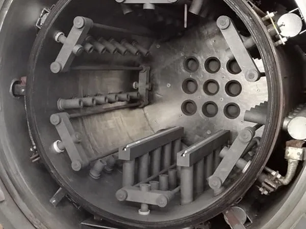
Element Shape and Configuration: Experiment with different graphite heating element designs (e.g., cylindrical, basket, plate, or rod configurations). The goal is to maximize the heated surface area and ensure uniform heat distribution within the chamber.
Material Grade: Use high-ppurity, high-density graphite for heating elements. Isotropic graphite often performs better due to its uniform thermal expansion and mechanical properties, reducing the risk of cracking and warpage.
Element Connections: Ensure robust and low-resistance electrical connections to the heating elements. Poor connections can lead to localized hot spots, power loss, and premature element failure.
2. Enhance Insulation Package:
Layered Insulation: Utilize a multi-layered insulation package consisting of various graphite felt, board, and foil materials. Each layer serves a purpose, with denser materials closer to the hot zone and less dense materials further out.
Reflective Foils: Incorporate graphite or carbon composite reflective foils between insulation layers. These foils significantly reduce heat loss through radiation.
Gap Management: Minimize gaps and pathways for heat bypass within the insulation. Proper baffling and interlocking designs can prevent thermal short-circuits.
Insulation Density and Thickness: Optimize the density and thickness of each insulation layer to balance thermal performance with chamber volume and cost.
3. Improve Temperature Uniformity:
Multi-Zone Heating: Implement a multi-zone heating system where different sections of the heating elements can be controlled independently. This allows for precise temperature profiling and compensation for heat losses at the ends or specific areas of the hot zone.
Gas Flow Dynamics (if applicable): If inert gas is used for cooling or partial pressure processes, optimize its introduction and circulation to avoid creating cold spots or uneven heating.
Thermocouple Placement: Strategically place multiple thermocouples throughout the hot zone to accurately map the temperature profile and provide feedback for control. Consider using optical pyrometers for very high temperatures where thermocouples might degrade.
Load Placement: Advise users on optimal load placement within the furnace to avoid shadowing effects and ensure even heating of the workpiece.

4. Advanced Control Systems:
PID Control with Auto-Tune: Utilize advanced Proportional-Integral-Derivative (PID) control systems with auto-tuning capabilities for precise temperature regulation and reduced overshoot/undershoot.
Ramp/Soak Programming: Implement sophisticated ramp/soak programming to define complex heating cycles, including precise heating rates, hold times, and cooling rates.
Data Logging and Analysis: Integrate data logging capabilities to monitor and record temperature profiles, vacuum levels, and power consumption. This data is crucial for process optimization and troubleshooting.
…
More detailed information on how to improve the performance of the graphite vacuum furnace heating chamber can be found here: https://www.czgraphite.com/a/news/improve-graphite-vacuum-furnace-heating-chamber-performance.html

