High-Gloss Printed Aluminum Coil for Beverage Can Packaging: Performance, Aesthetics, and Industrial Value

In the modern beverage packaging industry, visual appeal and functional performance are no longer separate priorities. Brands compete not only through taste and product quality but also through shelf impact and consumer perception. Among all packaging materials used in beverage cans, high-gloss printed aluminum coil has become one of the most critical solutions for achieving both premium appearance and reliable industrial performance. It combines advanced surface treatment, precision printing technology, and metallurgical stability to meet the demanding requirements of high-speed can production lines.

This article explains the technical value, manufacturing considerations, application advantages, and selection criteria of high-gloss printed aluminum coil for beverage can packaging. It is designed to help packaging engineers, procurement managers, and beverage brand owners make informed decisions based on real industrial needs.

1. Understanding High-Gloss Printed Aluminum Coil in Beverage Packaging

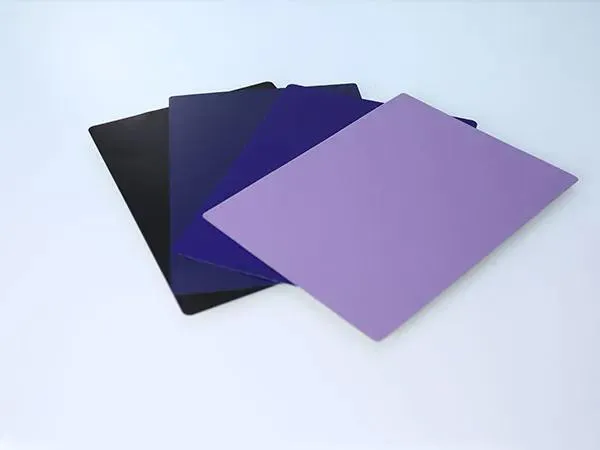
High-gloss printed aluminum coil refers to pre-coated aluminum sheet material that undergoes surface polishing, coating, and high-resolution printing before being formed into beverage cans. Unlike raw aluminum sheets, this material is processed to deliver both decorative and functional performance.

The aluminum substrate typically consists of alloys such as 3104 or 3105, which are widely used in can body applications due to their excellent formability, corrosion resistance, and strength-to-weight balance. After alloy selection and rolling processes, the coil is subjected to cleaning, coating, and printing stages that define its final visual and protective characteristics.

The high-gloss finish plays a crucial role in enhancing brand visibility. It creates a reflective surface that improves color vibrancy and sharpness of printed graphics, making beverage cans more attractive on retail shelves.
Printed Aluminum Coil

2. Manufacturing Process and Surface Engineering

The production of high-gloss printed aluminum coil involves several precision-controlled steps. Each stage directly influences final quality, especially in terms of gloss level, ink adhesion, and coating durability.

2.1 Surface Pretreatment

Before any coating is applied, the aluminum surface must be thoroughly cleaned and chemically treated. This process removes oxides, oils, and impurities that could affect adhesion. A conversion coating layer is then applied to improve corrosion resistance and ensure stable bonding between aluminum and subsequent coatings.

2.2 Base Coating Application

A base coat is applied to create a uniform surface and enhance brightness. This layer is engineered to support high-gloss reflection while maintaining compatibility with printing inks. The coating thickness must be precisely controlled to avoid defects such as uneven gloss or surface waviness.

2.3 High-Resolution Printing

Modern beverage packaging relies on high-definition printing technologies, typically using offset or gravure printing systems. These systems allow multi-color designs, gradient effects, and fine text reproduction. High-gloss aluminum coil enhances these prints by increasing contrast and saturation, making brand elements more visually striking.

…

For more information on high-gloss printed aluminum coils used in beverage can packaging, please click here: https://www.dw-al.com/a/news/high-gloss-printed-aluminum-coil-for-beverage-can-packaging.html
What are the Bending Properties of PVDF-Coated Printed Aluminum Coils, and What Factors Affect Their Performance?

In modern architectural decoration, transportation, and industrial manufacturing, PVDF coated printed aluminum coil has become one of the most widely used high-performance materials due to its excellent weather resistance, aesthetic versatility, and mechanical stability. Among all its performance indicators, bending performance plays a critical role because it directly determines whether the material can be safely formed, processed, and applied in real engineering environments without surface damage or structural failure.

Understanding the bending behavior of PVDF coated printed aluminum coil is essential for engineers, fabricators, and procurement specialists who aim to ensure durability, production efficiency, and long-term service reliability. This article provides a comprehensive analysis of its bending performance from a materials engineering perspective, including influencing factors, testing methods, application relevance, and selection considerations.

Understanding PVDF Coated Printed Aluminum Coil

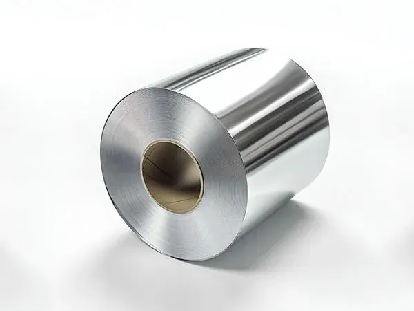
PVDF Coated Printed Aluminum Coil

PVDF coated printed aluminum coil is an aluminum substrate material that is coated with polyvinylidene fluoride (PVDF) resin and further processed with high-quality printing technology. The PVDF coating system is known for its exceptional chemical stability, UV resistance, and long service life, which makes it suitable for outdoor architectural applications such as curtain walls, roofing systems, and decorative facades.

The printed layer adds aesthetic value by allowing patterns such as wood grain, stone texture, metallic finishes, and customized graphic designs. However, beyond appearance, the mechanical integrity of the coating during forming processes, especially bending, determines whether the material can maintain its functional and visual performance after fabrication.

Importance of Bending Performance in Engineering Applications

Bending performance refers to the ability of coated aluminum coil to withstand deformation without cracking, peeling, whitening, or delamination of the coating layer. In real-world production, aluminum coils are often subjected to roll forming, folding, stamping, and bending into complex shapes.

If the coating system lacks sufficient flexibility or adhesion, surface defects may occur during processing, which can significantly reduce product quality and lifespan. Therefore, bending performance is not only a laboratory indicator but also a practical quality benchmark for industrial users.

For architectural applications, bending performance determines whether panels can be formed into curved façades or sharp-edged structures. In transportation and appliance industries, it affects manufacturability and assembly precision.

Key Factors Affecting Bending Performance

1. Aluminum Alloy Substrate Selection

The bending behavior of PVDF coated printed aluminum coil is strongly influenced by the mechanical properties of the aluminum substrate. Alloys such as 3003, 3105, and 5005 are commonly used due to their balanced strength and ductility. A substrate with higher elongation capacity generally provides better resistance to cracking during bending.

If the alloy is too hard or has insufficient ductility, micro-cracks may form under stress, which can propagate into the coating layer.

2. Coating Thickness and Structure

The PVDF coating system typically consists of a primer layer, a color coating layer, and a protective topcoat. The thickness and uniformity of these layers significantly influence flexibility.

…

For more detailed information on the bending properties of PVDF-coated printed aluminum coils and the influencing factors, please click to visit: https://www.dw-al.com/a/news/bending-performance-of-pvdf-coated-printed-aluminum-coil.html

Maximize Metal Purity with High-Density Graphite Crucibles

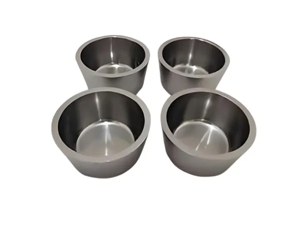
In precision metal casting and smelting, achieving the highest possible metal purity is paramount—whether you are refining precious metals, producing superalloys, or creating high-conductivity copper components. Impurities introduced during the melting process can degrade mechanical properties, electrical conductivity, and corrosion resistance of the final product. The choice of crucible material plays a decisive role in this equation. High-density graphite crucibles have emerged as the preferred solution for maximizing metal purity, thanks to their unique combination of thermal stability, chemical inertness, and low porosity. This article delves into the science behind how these crucibles preserve metal quality and provides actionable guidance for selecting the right crucible for your application.

Why Crucible Material Directly Affects Metal Purity

The crucible is more than a container; it is a reactive vessel that interacts with molten metal at extreme temperatures. Conventional crucibles made from clay-graphite or silicon carbide often contain binders and additives that can leach into the melt, introducing contaminants such as silica, iron oxides, or aluminum. In contrast, high-density graphite crucibles are manufactured from nearly pure carbon with minimal binder residue, significantly reducing the risk of elemental contamination. The density—typically exceeding 1.85 g/cm³—means fewer open pores, which limits gas absorption and minimizes slag entrapment. For applications requiring ultra-high purity, such as aerospace alloys or electronic-grade copper, this distinction can mean the difference between meeting specifications and costly rejection.

Key Advantages of High-Density Graphite Crucibles for Purity

1. Extremely Low Porosity Prevents Oxidation and Inclusions

Porosity is the enemy of metal purity. Lower-density crucibles allow oxygen and other gases to penetrate the crucible wall, reacting with the melt to form oxides that become inclusions. High-density graphite, with porosity below 10%, acts as a virtually impermeable barrier, keeping the melt isolated from furnace atmosphere. This is especially critical when melting reactive metals like titanium or zirconium, where even trace oxygen can cause embrittlement.

2. Superior Thermal Shock Resistance Maintains Structural Integrity

Rapid heating and cooling cycles can cause conventional crucibles to crack, releasing particles into the melt. High-density graphite exhibits excellent thermal conductivity (over 100 W/mK) and a low coefficient of thermal expansion, enabling it to withstand severe thermal gradients without fracture. Cangzhou Carbon manufactures high-density crucibles with a fine-grained microstructure that further enhances crack resistance, ensuring that no material flakes contaminate your metal.

3. Minimal Reactivity with Most Molten Metals

Graphite is thermodynamically stable in many molten metals, particularly non-ferrous alloys like aluminum, copper, bronze, and gold. Unlike ceramic crucibles that can dissolve or react, high-density graphite remains inert up to 3000°C in controlled atmospheres. This non-wetting behavior means less metal adhesion to the crucible walls, reducing cross-contamination between melts and simplifying cleaning.

Comparing High-Density Graphite to Alternative Crucible Materials

To make an informed decision, it is helpful to see how high-density graphite stacks up against other common crucible materials:

  • Clay-Graphite Crucibles: Lower cost but higher porosity (15-20%) and binder-related impurities. Suitable for general casting but not for purity-critical applications.
  • Silicon Carbide Crucibles: Good thermal shock resistance but can react with certain metals (e.g., nickel) and may release silicon into the melt.

…

For more detailed information on maximizing metal purity using high-density graphite crucibles, please click here: https://www.czgraphite.com/a/news/maximize-metal-purity-with-high-density-graphite-crucibles.html

Isostatically Pressed Graphite for Vacuum Furnace Components: A Practical Guide for Engineers and Buyers

Vacuum furnace performance depends heavily on the stability and reliability of internal components, and material selection plays a decisive role in achieving consistent results. Many manufacturers and engineers choose isostatically pressed graphite because it delivers a balanced combination of purity, strength, and thermal stability under extreme conditions. This article explains why isostatically pressed graphite stands out, how it is used in vacuum furnace components, and what decision-makers should consider before sourcing it.

What Is Isostatically Pressed Graphite?

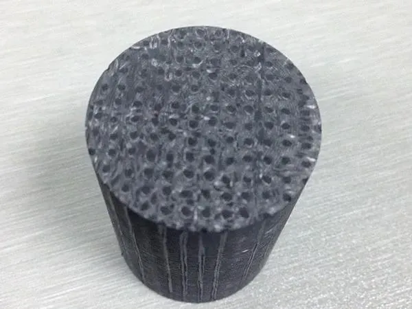
Isostatically pressed graphite is produced by applying uniform pressure to fine graphite powder in all directions during the forming process. This manufacturing method creates a highly uniform microstructure with minimal anisotropy. Compared with extruded or molded graphite, isostatic graphite offers superior density consistency, mechanical strength, and isotropic properties.

Manufacturers rely on this process when they need materials that can perform predictably in high-temperature and high-vacuum environments. The uniform grain structure ensures that the material behaves consistently regardless of orientation, which is critical for precision furnace components.

isostatically pressed graphite

Why Vacuum Furnaces Require High-Performance Graphite

Vacuum furnaces operate in demanding environments that involve high temperatures, low pressure, and strict contamination control. Engineers must select materials that can withstand these conditions without degrading or introducing impurities.

Isostatically pressed graphite meets these requirements in several ways:

It provides excellent thermal conductivity, which helps maintain uniform temperature distribution.

It offers high resistance to thermal shock, allowing components to handle rapid heating and cooling cycles.

It ensures low outgassing rates, which protects the vacuum environment from contamination.

It maintains structural integrity at temperatures exceeding 2000°C in inert or vacuum atmospheres.

Because of these advantages, industries such as aerospace, metallurgy, semiconductor processing, and tool manufacturing widely adopt this material.

Common Applications in Vacuum Furnace Components

Engineers design a wide range of furnace components using isostatically pressed graphite. Each application benefits from the material’s stability and precision.

1. Heating Elements

Heating elements require materials that can withstand extreme temperatures without deformation. Isostatic graphite ensures stable resistance and long service life, which reduces downtime and replacement costs.

2. Insulation Components

Graphite felt and rigid boards made from isostatic graphite help improve thermal efficiency. These materials reduce heat loss and maintain energy efficiency inside the furnace chamber.

3. Fixtures and Trays

Furnace fixtures must support workpieces without warping or contaminating them. Isostatic graphite provides dimensional stability and chemical inertness, which ensures product quality.

…

For more detailed information on the practical guide to isostatic graphite for vacuum furnace components, please click here: https://www.czgraphite.com/a/news/isostatically-pressed-graphite-for-vacuum-furnace-components.html

High-Purity Graphite vs. Carbon-Carbon Composites for Heat Treatment: A Practical Selection Guide

Heat treatment environments demand materials that can survive extreme temperatures, resist chemical attack, and maintain dimensional stability over long production cycles. Engineers and procurement teams often face a key decision: should they choose high-purity graphite or carbon-carbon (C/C) composites for fixtures, insulation components, and structural parts inside furnaces?

This article provides a clear, experience-driven comparison of these two materials. It explains how each performs in real industrial conditions and helps you select the right option based on temperature range, atmosphere, mechanical load, and lifecycle cost.

Understanding the Materials

carbon-carbon (C/C) composites

What Is High-Purity Graphite?

High-purity graphite is a refined form of carbon with a purity level typically above 99.9%. Manufacturers produce it through high-temperature graphitization processes, which remove impurities and enhance thermal stability. Its structure consists of layered carbon planes, which provide excellent thermal conductivity and machinability.

This material is widely used in vacuum furnaces, sintering systems, and crystal growth applications because it combines thermal resistance with relatively low cost and easy processing.

What Are Carbon-Carbon Composites?

Carbon-carbon composites are engineered materials made by reinforcing carbon fibers within a carbon matrix. This structure gives them exceptional strength, especially at high temperatures. Unlike traditional graphite, C/C composites maintain mechanical integrity even under thermal shock and heavy loads.

Industries such as aerospace and advanced metallurgy rely on these materials for extreme applications where failure is not an option.

Performance Comparison in Heat Treatment Applications

1. Temperature Resistance

Both materials perform well at high temperatures, but their limits differ in practical use.

High-purity graphite performs reliably in temperatures up to 3000°C in inert or vacuum environments. However, it becomes more fragile as temperature rises, especially under mechanical stress.

Carbon-carbon composites can also withstand temperatures above 3000°C, but they maintain structural strength far better at elevated temperatures. This advantage becomes critical in applications involving repeated thermal cycling or mechanical loading.

Key takeaway: If your process involves static components, graphite is sufficient. If your components experience stress or movement at high temperature, C/C composites offer better reliability.

2. Mechanical Strength and Durability

Graphite is inherently brittle. While it is easy to machine into complex shapes, it can crack or chip under impact or load.

Carbon-carbon composites, on the other hand, provide superior tensile strength, flexural strength, and fracture resistance. Their fiber-reinforced structure prevents sudden failure and extends service life.

Practical implication: Fixtures, trays, and load-bearing structures benefit significantly from C/C composites, especially in automated or high-throughput furnaces.

3. Thermal Shock Resistance

Thermal shock occurs when materials experience rapid temperature changes. This is common in heat treatment processes such as quenching or fast heating cycles.

Graphite has decent thermal shock resistance due to its low thermal expansion. However, it can still develop microcracks over time.

Carbon-carbon composites excel in this area. Their fiber structure absorbs thermal stress and prevents crack propagation.

Conclusion: For processes involving frequent heating and cooling cycles, C/C composites reduce failure rates and maintenance downtime.

4. Purity and Contamination Control

High-purity graphite is specifically designed for environments where contamination must be minimized. It is widely used in semiconductor and precision metallurgy applications.

Carbon-carbon composites may contain residual binders or impurities depending on the manufacturing process. While high-grade C/C materials can achieve excellent purity, they often require additional treatment.

…

For more detailed information on the application guidelines of high-purity graphite and carbon-carbon composites in heat treatment, please click to visit:https://www.czgraphite.com/a/news/high-purity-graphite-vs-carbon-carbon-composites-for-heat-treatment.html

How Crossed Roller Bearings Boost Robot Joint Precision

In modern robotics, joint precision is the cornerstone of repeatable motion, load handling, and overall system reliability. As robots are deployed in high-stakes environments such as medical surgery, semiconductor manufacturing, and collaborative assembly, even micron-level errors can lead to costly defects or safety risks. Crossed roller bearings have emerged as a critical enabler of this precision, offering a unique combination of rigidity, low friction, and multi-axis load support. This article explores the technical principles behind crossed roller bearings, how they directly improve robot joint performance, and why PRS has become a trusted partner for engineers seeking maximum accuracy and durability.

Understanding Crossed Roller Bearings: A Technical Overview

Design and Construction

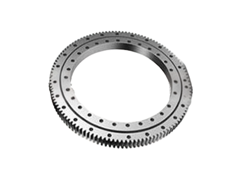
Unlike conventional ball bearings that rely on point contact, crossed roller bearings use cylindrical rollers arranged in a crossed pattern between inner and outer rings. Each roller acts like a miniature beam, distributing loads over a line of contact rather than a single point. This design allows the bearing to simultaneously handle radial, axial, and moment loads with minimal elastic deformation. The rollers are typically separated by a cage or spacer to prevent friction between adjacent rollers, ensuring smooth and consistent motion even under high preload.

Key Distinguishing Features

The most significant feature of crossed roller bearings is the 90-degree roller orientation. This configuration creates a highly rigid structure that resists tilting and twisting forces. Additionally, the absence of a conventional ball raceway eliminates the “ball spin” phenomenon, which causes uneven wear and position loss over time. The result is a bearing that maintains its original accuracy throughout its service life, a critical requirement for robotics applications where recalibration is costly or impractical.

The Critical Role of Precision in Robot Joints

Impact of Bearing Accuracy on Repeatability and Stiffness

Robot joints are subjected to complex, multi-directional loads: gravitational forces from the arm, inertial forces from acceleration, and external forces from tool contact. A bearing that deflects even a few microns under these loads will cause cumulative positioning errors, especially in articulated arms with multiple joints. Crossed roller bearings provide nearly zero radial and axial runout, typically maintaining tolerance classes within 2–5 µm. This translates directly to higher repeatability—the ability to return to a programmed position with extreme consistency—and stiffness, which prevents oscillation or overshoot during high-speed motion.

…

For more detailed information on how crossed roller bearings can improve robot joint precision, please click to visit:https://www.prsbearings.com/a/news/how-crossed-roller-bearings-boost-robot-joint-precision.html

Crossed Roller Bearing vs. Angular Contact Ball Bearing: Which Is Better for Rigidity?

When engineers evaluate bearing solutions for high-precision equipment, rigidity becomes a decisive factor rather than just a performance metric. Whether the application involves CNC machine tools, industrial robots, medical devices, or semiconductor equipment, insufficient rigidity often leads to vibration, positioning errors, and premature wear. This article explains the real differences between crossed roller bearings and angular contact ball bearings, with a strong focus on rigidity, helping you make a technically sound and commercially practical choice.

Understanding Rigidity in Bearing Applications

Rigidity refers to a bearing’s ability to resist deformation under load. In practical terms, it determines how much displacement occurs when forces act on the system. A bearing with high rigidity maintains positional accuracy, reduces deflection, and improves machining quality or motion stability.

Rigidity depends on several factors:

Contact geometry between rolling elements and raceways

Internal clearance or preload

Material properties and heat treatment

Load direction and distribution

Both crossed roller bearings and angular contact ball bearings are designed for precision applications, but their internal structures lead to very different rigidity characteristics.

What Is a Crossed Roller Bearing?

A crossed roller bearing features cylindrical rollers arranged orthogonally (at 90 degrees) between inner and outer rings. Each roller alternates in orientation, allowing the bearing to handle radial, axial, and moment loads simultaneously.

Key Structural Advantage

Because rollers have line contact with raceways, the load distributes over a larger contact area compared to point contact in ball bearings. This design significantly increases stiffness.

Rigidity Performance

Crossed roller bearings typically deliver:

Extremely high rigidity under multi-directional loads

Minimal elastic deformation

Superior resistance to tilting moments

This makes them ideal for applications where even micron-level deflection is unacceptable.

What Is an Angular Contact Ball Bearing?

An angular contact ball bearing uses balls as rolling elements, with raceways designed to support loads at a specific contact angle. These bearings are often installed in pairs or sets to handle combined loads.

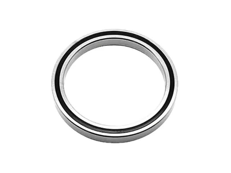
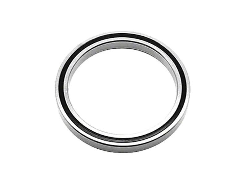
crossed roller bearings

Key Structural Advantage

The point contact between balls and raceways reduces friction and allows for higher rotational speeds. Engineers often use preload configurations to enhance stiffness.

Rigidity Performance

Angular contact ball bearings provide:

Moderate to high rigidity depending on preload

Good axial load support in one direction (or both when paired)

Flexibility in configuration (back-to-back, face-to-face, tandem)

However, due to point contact, their inherent rigidity is lower than that of roller-based designs.

…

For more detailed information about crossed roller bearings and angular contact ball bearings, please click to visit: https://www.prsbearings.com/a/news/difference-between-crossed-roller-bearings-and-angular-contact-ball-bearings.html

How is the Load Capacity of Slim-Type Crossed Roller Bearings Calculated, and What Are the Influencing Factors?

Slim-type crossed roller bearings have become a preferred solution in industries that demand high precision, compact design, and reliable load performance. Engineers who work with robotics, automation systems, medical devices, and CNC equipment often select these bearings because they deliver exceptional rigidity while maintaining a slim profile. However, many users still struggle to fully understand how load capacity works in these specialized bearings and how to select the right model for their application.

This guide explains the load capacity of slim-type crossed roller bearings in a clear, practical, and experience-driven way. It focuses on real engineering considerations rather than textbook definitions, helping you make informed decisions that improve equipment performance and service life.

What Are Slim-Type Crossed Roller Bearings?

Slim-type crossed roller bearings are a variation of crossed roller bearings designed with a reduced cross-section. Manufacturers arrange cylindrical rollers orthogonally (at 90 degrees) between inner and outer rings. This structure allows a single bearing to simultaneously handle radial loads, axial loads, and moment loads.

Unlike traditional bearings that require multiple units to support different load directions, slim-type crossed roller bearings simplify system design. Their compact structure makes them ideal for applications where space and weight constraints are critical.

Slim-Type Crossed Roller Bearings

Load Capacity of Slim-Type Crossed Roller Bearings

Load capacity is not a single fixed value. Engineers typically evaluate it through two main parameters:

Dynamic Load Capacity (C): This value represents the load a bearing can handle during rotation over a defined lifespan.

Static Load Capacity (C₀): This value indicates the maximum load a bearing can withstand without permanent deformation when stationary.

Slim-type crossed roller bearings often show high load capacity relative to their size. However, actual performance depends heavily on operating conditions, installation accuracy, and load distribution.

Key Factors That Affect Load Capacity

1. Bearing Geometry and Roller Arrangement

The crossed arrangement of rollers ensures that load is distributed evenly across multiple contact points. This design significantly increases rigidity and load-bearing capability compared to standard ball bearings.

Slim-type designs, however, reduce material thickness. Engineers must balance compactness with strength. A thinner ring structure may slightly reduce absolute load capacity, but optimized internal geometry compensates for this in most applications.

2. Material Quality and Heat Treatment

High-quality bearing steel and precise heat treatment processes directly influence load capacity. Manufacturers who control hardness, residual stress, and microstructure can significantly enhance fatigue resistance.

In real-world applications, bearings made with inferior materials often fail prematurely, even if their catalog load ratings appear similar. This is why sourcing from reliable manufacturers is critical for long-term performance.

…

To learn more about how to calculate the load capacity of slim crossed roller bearings and what factors affect load capacity, please click to visit: https://www.prsbearings.com/a/news/load-capacity-of-slim-type-crossed-roller-bearings.html

How to Choose a Jaw Crusher That Handles Hard Rock Efficiently

Selecting the right jaw crusher for hard rock applications is one of the most critical decisions in any mining or aggregate operation. Hard rock—such as granite, basalt, or quartzite—places extreme stress on crushing components, demanding a machine that combines robust construction, optimized kinematics, and reliable performance. An unsuitable crusher leads to frequent downtime, excessive wear, and ultimately higher operating costs. This guide breaks down the essential factors you must evaluate to choose a jaw crusher that handles hard rock efficiently, with practical insights backed by engineering principles. By the end, you will have a clear framework to match your material and production requirements to the right machine, and understand why YUDE has become a trusted name in this demanding field.

Understanding the Mechanical Demands of Hard Rock Crushing

Hard rock typically exhibits compressive strengths exceeding 200 MPa (29,000 psi). A jaw crusher designed for such material must withstand immense forces without structural failure. Key mechanical elements include:

  • Heavy-duty frame: A thick, stress-relieved steel frame with reinforcements at critical stress points ensures rigidity and long-term alignment.
  • Deep crushing chamber: For hard rock, a deep V-shaped cavity allows the feed to be gripped earlier and reduces slip. This design maximizes the crushing ratio while minimizing wear on the fixed and moving jaws.
  • Oversized eccentric shaft: A large-diameter shaft with high-quality alloy steel provides the necessary flywheel momentum to fracture hard rock consistently.
  • Toggle plate and hydraulic relief: A robust toggle mechanism with tramp iron relief (often hydraulic) protects the crusher from uncrushable materials.

When evaluating a crusher, review its structural components and confirm that the manufacturer uses finite element analysis (FEA) to optimize the frame design. YUDE, for example, employs FEA in all their jaw crusher models to ensure maximum fatigue life even under continuous hard rock service.

Key Features That Define Efficiency in Hard Rock Processing

Not all jaw crushers are created equal. Below is a comparison of traditional versus modern designs that excel in hard rock applications:

…

For more detailed information on how to choose a jaw crusher capable of efficiently handling hard rock, please click here: https://www.yd-crusher.com/a/news/choose-jaw-crusher.html

Why Is My Jaw Crusher Vibrating Excessively? A Practical Guide for Operators and Buyers

Excessive vibration in a jaw crusher is not just an annoyance—it often signals underlying mechanical or operational issues that can reduce efficiency, accelerate wear, and even lead to unexpected downtime. Many operators initially assume that vibration is a normal byproduct of crushing, but when it becomes abnormal, the machine is essentially “communicating” a problem that should not be ignored.

This article explains the real causes behind excessive vibration in jaw crushers, how to diagnose them, and what practical steps you can take to solve the issue. Whether you are an equipment operator, maintenance engineer, or procurement manager, this guide will help you make informed decisions and maintain stable production.

1. Understanding Normal vs. Abnormal Vibration

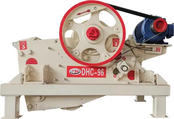
Every jaw crusher generates a certain level of vibration due to its working principle. The eccentric shaft drives the movable jaw to crush materials through periodic motion, which naturally produces dynamic forces.

However, normal vibration is stable and consistent, while excessive vibration often shows the following signs:

Sudden increase in amplitude

Irregular or intermittent shaking

Noise changes or metallic knocking

Visible movement of the foundation or frame

If your crusher shows any of these symptoms, the issue usually lies in mechanical imbalance, improper installation, or incorrect operation.

2. Common Causes of Excessive Vibration

2.1 Uneven or Improper Feeding

One of the most overlooked causes is uneven feeding. When materials enter the crushing chamber from one side or in inconsistent volumes, the load distribution becomes unbalanced.

This imbalance forces the movable jaw to operate under uneven stress, which leads to vibration.

How to fix it:

Use a vibrating feeder to ensure uniform feeding

Avoid dumping large batches suddenly

Maintain consistent feed size and flow

2.2 Loose Foundation or Anchor Bolts

A jaw crusher must be installed on a solid and stable foundation. If anchor bolts loosen over time or the concrete base develops cracks, the entire machine can shift during operation.

…

For more detailed information on the causes and solutions for excessive vibration in jaw crushers, please click to visit: https://www.yd-crusher.com/a/news/causes-and-solutions-for-excessive-vibration-in-jaw-crushers.html