
Radial vs Axial Load Capacity in Roller Bearings
Roller bearings rarely fail because someone picked the wrong catalog number. They fail because the load direction was misunderstood. A bearing that handles a heavy radial load with ease can be destroyed surprisingly fast by a modest axial thrust, and the reverse is equally true. Engineers comparing radial versus axial load capacity in roller bearings are usually trying to answer one practical question: which rolling element geometry matches the forces in my application, and how much of each direction can it realistically carry? The answer depends on contact angle, raceway geometry, roller length-to-diameter ratio, and how the load is distributed across the loaded zone. This guide breaks down the mechanics, compares the major roller bearing families, and explains how to read load ratings before committing to a design.
Radial and Axial Loads: Two Directions, Two Different Mechanisms
The distinction sounds trivial until you look at how the rolling elements actually react. A radial load pushes the shaft perpendicular to its centerline, while an axial load pushes it along the centerline. Those two force vectors engage completely different parts of the bearing’s internal geometry.
How radial loads travel through a roller bearing
Under a purely radial load, roughly half the rollers in a typical bearing carry the load, forming a load zone that spans about 180 degrees of the raceway circumference. Each loaded roller deforms slightly against both rings, and the resulting contact stress is spread along the full roller length. Because cylindrical rollers make line contact rather than point contact, the load is distributed across a much larger area than in a ball bearing of similar size. That is the fundamental reason roller bearings achieve high radial capacity in a compact envelope.
How axial loads travel through a roller bearing
An axial load cannot simply be pressed into a cylindrical raceway. It has to be redirected by geometry. There are only two ways to do this: build a contact angle into the bearing so the roller axis is tilted relative to the shaft axis, or use flanges and thrust shoulders that guide the roller ends. In a tapered roller bearing, the contact angle converts part of the axial thrust into a radial reaction at the cone back face and cup face. In a cylindrical roller bearing with a fixed rib, the axial load is taken by sliding contact between the roller end face and the rib, which is a fundamentally different and far more limited load path.
Combined loads are the normal case
Pure radial or pure axial loading is mostly a textbook simplification. Gear drives, pulley arrangements, and inclined shafts all produce combined loading with a moment component. In these situations the bearing is evaluated against an equivalent dynamic load that weights the radial and axial components according to the bearing’s X and Y factors, and against an equivalent static load for peak or shock conditions. The X and Y factors come from the bearing manufacturer and vary with the ratio of axial to radial load and with the contact angle.
Which Roller Bearing Type Handles Which Load Direction
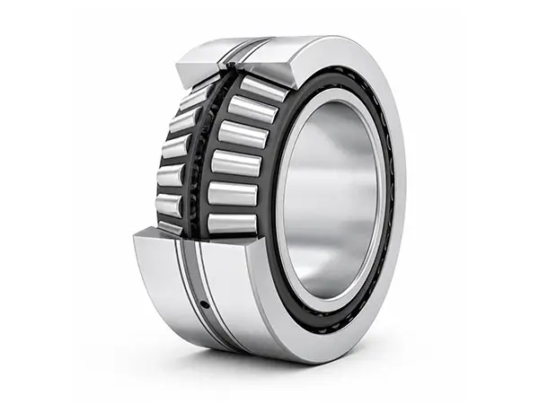
Roller bearing families are not interchangeable when thrust is present. The table below summarizes how each type behaves, followed by the practical consequences.
- Cylindrical roller bearings (NU, NJ, NUP, N designs): Very high radial capacity, essentially zero axial capacity in the basic NU/N design. NJ and NUP variants with ribs accept limited axial loads in one or both directions, but only at low to moderate levels and with careful attention to lubrication of the rib contact.
- Tapered roller bearings: High radial capacity combined with substantial axial capacity in one direction per bearing. Mounted in pairs or opposed arrangements they take thrust in both directions. The induced axial force generated by the contact angle must be accounted for in the arrangement calculation.
…
For more detailed information regarding the radial and axial load-carrying capacities of roller bearings, please click here: https://www.chgbearingtech.com/blog/radial-axial-load/


