Why Jaw Crushers Outperform Cone Crushers for Primary Crushing

Selecting the right crusher for primary crushing is a critical decision that directly impacts downstream efficiency, capital expenditure, and operational costs. While cone crushers are widely used in secondary and tertiary stages, many operators overlook the fundamental advantages of jaw crushers in the primary role. This article provides a professional, data-driven comparison to explain why jaw crushers consistently outperform cone crushers for primary crushing applications, and how YUDE engineering solutions maximize these benefits.

1. Fundamental Design Differences Suited for Primary Duty

The primary crusher must handle the largest, hardest, and most irregularly shaped feed material directly from the mine or quarry. Jaw crushers employ a straightforward compression mechanism: a fixed jaw and a moving jaw create a wedge-shaped chamber. This design excels at accepting oversized rocks without bridging or blockage.

Why Jaw Crushers Handle Oversize Better

A jaw crusher’s feed opening is rectangular and significantly wider than a cone crusher’s bowl. For example, a typical 30×48 jaw crusher can accept boulders up to 700 mm, while a cone crusher of similar horsepower requires prescreening or grizzly feeder to avoid jamming. Jaw crushers have a higher tolerance for non-uniform feed—blasted rock with sharp edges, elongated slabs, and clay content can pass through, whereas a cone crusher’s annular chamber would clog or cause excessive wear.

  • Cone crusher limitation: Requires choke feeding and even distribution to maintain stable operation.
  • Jaw crusher advantage: Capable of intermittent, surge feeding common in primary circuits.

2. Superior Throughput for Coarse Reduction Ratios

Primary crushing demands a reduction ratio of 4:1 to 6:1. Jaw crushers naturally achieve this in a single pass. Cone crushers, designed for finer reduction (6:1 to 8:1), often require a larger closed side setting (CSS) to avoid overload, resulting in lower throughput and higher recirculating loads.

For more information about jaw crushers being superior to cone crushers in primary crushing, please click to visit:https://www.yd-crusher.com/a/news/jaw-vs-cone-primary.html

Crossed Roller Bearings: High Rigidity in a Thin Package

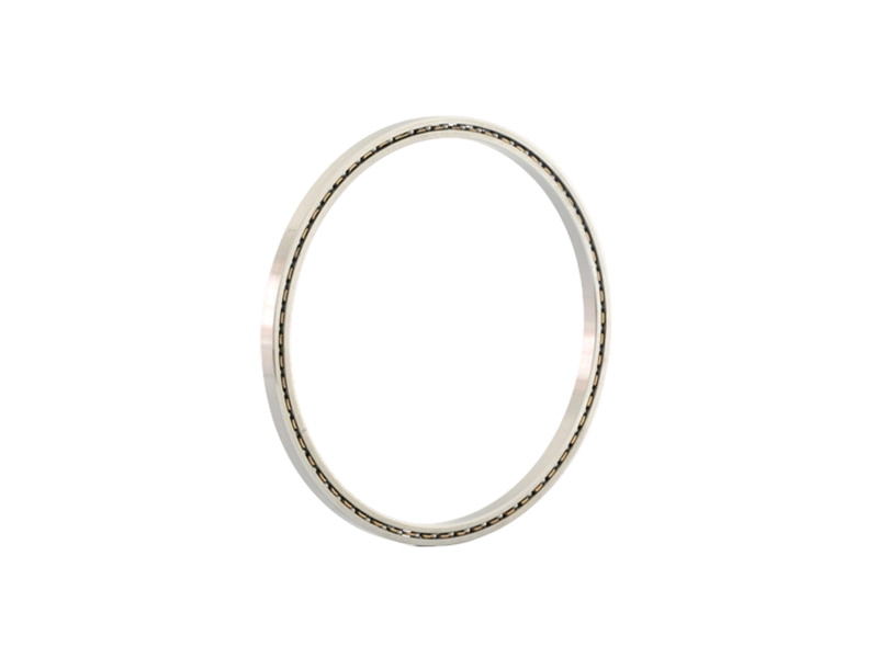
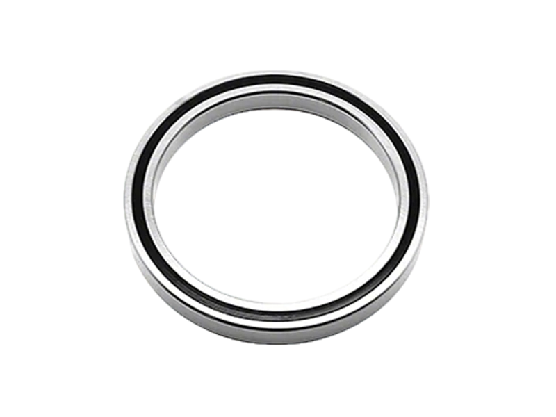
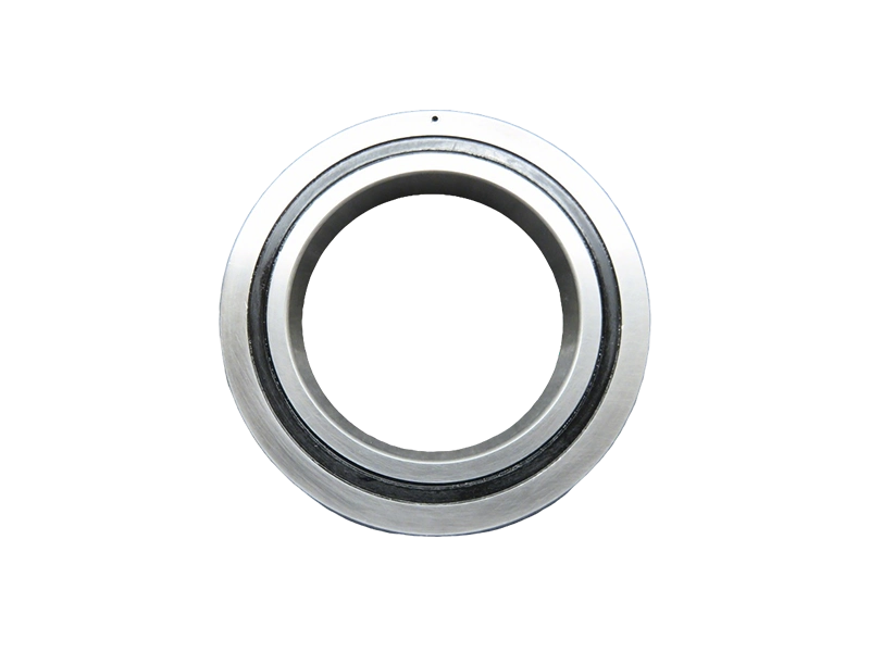
When engineers face the challenge of achieving maximum rigidity within a confined axial space, traditional bearing solutions often fall short. Crossed roller bearings offer a compelling answer—combining the load-carrying capacity of roller bearings with a remarkably thin cross-section. Unlike ball bearings or conventional crossed roller designs, the unique roller arrangement in these bearings provides high stiffness in multiple directions while reducing overall installation height. For applications where every millimeter matters—such as robotics, medical imaging, and machine tool rotary tables—this technology has become indispensable. In this article, we explore the mechanical principles, performance advantages, and practical considerations when specifying Crossed Roller Bearings, with a focus on PRS solutions that have gained recognition in demanding industrial environments.

Understanding the Structure and Working Principle

A crossed roller bearing consists of cylindrical rollers arranged in alternating perpendicular directions (0° and 90°) between two raceways. This orthogonal arrangement allows the bearing to support radial, axial, and moment loads simultaneously with minimal clearance. The rollers are separated by a cage or spacer to prevent metal-to-metal contact, reducing friction and wear.

Why Crossed Arrangement Improves Rigidity

In a standard roller bearing, all rollers are parallel, limiting the direction of load support. By crossing the rollers at 90°, the bearing can resist forces from multiple axes without requiring additional bearings. This design inherently provides higher stiffness because the contact area between each roller and the raceway is a line (rather than a point in ball bearings), distributing the load over a larger surface. The result is a bearing that can handle significant tilting moments while maintaining extremely low rotational resistance.

Thin Package: The Cross-Sectional Advantage

The term “thin package” refers to the bearing’s minimal radial and axial cross-section relative to its diameter. Crossed roller bearings are typically produced with a rectangular or square cross-section that is small compared to the bore diameter—often in the range of 5 mm to 20 mm wide for bearings up to 1 meter in diameter. This compactness is achieved by eliminating the need for separate thrust and radial bearings. Engineers can integrate the bearing into a narrow annular space, reducing overall system weight and size.

Key Performance Benefits Over Alternative Bearing Types

When deciding between crossed roller bearings, ball bearings, and other roller variants, several performance metrics favor the crossed roller design:

  • High Rigidity Under Combined Loads: The orthogonal rollers create a stiff ‘X’ structure that resists both axial and radial forces. Unlike ball bearings, which only offer point contact, the line contact of crossed rollers reduces elastic deformation under load. This is critical for precision positioning in CNC machines and inspection equipment.

For more information on the slim, lightweight, and high-rigidity design of crossed roller bearings, please click here:https://www.prsbearings.com/a/news/crossed-roller-beari.html

Solving Rotary Table Deflection: Crossed Roller Bearing Use

Rotary tables are the backbone of precision machining, assembly, and inspection equipment. When a rotary table deflects under load, it introduces angular errors that compromise part accuracy, repeatability, and surface finish. Engineers often struggle to balance stiffness, compactness, and load capacity. Crossed roller bearings have emerged as a proven mechanical solution to mitigate deflection without sacrificing space or weight. This article examines the root causes of rotary table deflection, explains how the unique geometry of crossed roller bearings counteracts these forces, and provides practical guidance for incorporating them into your design. For over a decade, PRS has specialized in precision crossed roller bearing solutions, and the principles discussed here reflect industry-proven practices.

Understanding Rotary Table Deflection: Causes and Consequences

Rotary table deflection occurs when external forces—axial, radial, or moment loads—cause the table to tilt or shift from its ideal axis of rotation. In machining centers, this deflection typically arises from cutting forces; in measurement equipment, it results from workpiece weight or inertial forces during indexing. The primary mechanical contributors are:

  • Bearing clearance: Even minimal play in conventional ball bearings allows the table to rock under moment loads.
  • Limited stiffness: Single-row ball or roller bearings have lower radial and moment stiffness compared to crossed configurations.
  • Elastic deformation: Under heavy combined loads, the bearing raceways and rolling elements deform, leading to micro-deflections.

The consequences are significant: increased part rejection, shortened tool life, and reduced machine uptime due to rework. Understanding deflection modes is the first step to selecting a bearing that eliminates them at the source.

How Crossed Roller Bearings Solve Deflection

Crossed roller bearings differ fundamentally from conventional bearings. They consist of cylindrical rollers arranged alternately at 90-degree angles between inner and outer rings. This crossed arrangement creates a rigid, preloaded assembly that resists deflection in all directions simultaneously.

For more information on the application of crossed roller bearings in solving turntable deflection problems, please click to visit:https://www.prsbearings.com/a/news/solving-rotary-deflection.html

Achieve Sub-Arc-Second Accuracy with Crossed Roller Bearing

Achieving sub-arc-second accuracy in rotational motion is the defining challenge for engineers designing the next generation of precision equipment—from wafer handling robots to goniometric stages used in synchrotron beamlines. Traditional bearing technologies often fall short due to inherent clearance, compliance, or kinematic errors. Crossed roller bearings have emerged as the mechanical foundation that makes sub-arc-second positioning not just possible, but repeatable and reliable. This article examines the engineering principles behind this performance, compares crossed roller bearings with other precision bearing types, and illustrates how PRS’s design expertise helps customers reach the 0.1 arc-second threshold in real-world applications.

Understanding Sub-Arc-Second Accuracy and Its Mechanical Hurdles

Sub-arc-second accuracy refers to angular positioning errors smaller than one arc-second (1/3600 of a degree). For a rotary table with a 200 mm diameter, a 0.5 arc-second error corresponds to a linear displacement of roughly 0.5 μm at the circumference. Achieving this level demands bearings with absolute minimum runout, friction variation, and elastic deformation.

Why Conventional Bearings Struggle

Ball bearings rely on point contact, which leads to high Hertzian stresses and noticeable elastic deformation under load. Even preloaded angular contact ball bearings exhibit variations in contact angle and cage instability that produce periodic errors in the sub-arc-second range. Crossed roller bearings, by contrast, use line contact between cylindrical rollers arranged alternately at 90° angles. This geometry provides high stiffness in all radial, axial, and moment loading directions with minimal deflection—a prerequisite for sub-arc-second stability.

The Crossed Roller Bearing Design That Enables Sub-Arc-Second Performance

The key design feature of a crossed roller bearing is its roller arrangement: each roller is rotated 90° relative to its neighbor, with a separator (cage) maintaining precise spacing. This orthogonal orientation allows the bearing to absorb combined loads and constrain all degrees of freedom except rotation. When combined with precision-ground raceways and optimized preload, the result is a bearing with virtually zero clearance and highly uniform rolling resistance.

For more information on achieving sub-arcsecond accuracy using crossed roller bearings, please click to visit:https://www.prsbearings.com/a/news/sub-arc-second-accur.html

Crossed Roller Bearings vs Angular Contact: Key Differences

When designing precision rotary tables, robotic joints, or machine tool spindles, engineers often face a critical decision: crossed roller bearings versus angular contact ball bearings. Both provide high accuracy and rigidity, but their structural differences lead to distinct performance characteristics in load handling, stiffness, and space utilization. Understanding these differences is essential for selecting the optimal bearing arrangement for your specific application, whether it demands moment load resistance, compactness, or high-speed capability. This article provides a detailed comparison to guide your selection process, with insights drawn from PRS’s extensive experience in precision bearing manufacturing.

1. Understanding the Basic Structures

Crossed Roller Bearings

Crossed roller bearings consist of cylindrical rollers arranged in a cross pattern—typically with alternating rollers oriented at 90 degrees to each other within a single raceway. This unique design enables the bearing to handle radial, axial, and moment loads simultaneously from any direction. The rollers are separated by spacers (or a retainer) to prevent friction between them. Because the contact surface between the roller and raceway is a line (rather than a point), the load capacity per unit area is high. PRS offers crossed roller bearings in both inner-ring rotation and outer-ring rotation configurations, with options for integral sealing and preload adjustment.

Angular Contact Ball Bearings

Angular contact ball bearings feature balls running on raceways that are angled relative to the bearing axis. This angle (typically 15°, 25°, or 40°) allows the bearing to accommodate combined radial and axial loads. They are usually used in pairs (back-to-back, face-to-face, or tandem) to achieve bidirectional thrust capacity and increased rigidity. The contact between the ball and raceway is a point, which results in lower friction but also lower load capacity compared to roller bearings of similar size. Angular contact bearings are widely used in high-speed spindles and precision mechanisms where low heat generation is critical.

2. Load Capacity and Stiffness Comparison

The most decisive difference between these two bearing types lies in how they handle loads, particularly moment (tilting) loads and combined loads.

For more information on the main differences between crossed roller bearings and angular contact bearings, please click to visit:https://www.prsbearings.com/a/news/difference-between-crossed-roller-bearings-and-angular-contact-bearings.html

Why Compact Robot Arms Need Crossed Roller Bearings

The push toward miniaturization in automation has placed unprecedented demands on robot arm design. Smaller, lighter, and faster—these compact robot arms must maintain exceptional precision and stiffness while operating in increasingly tight spaces. At the heart of this engineering challenge lies a critical component: the bearing. Traditional ball bearings often fall short in meeting the combined requirements of high moment load capacity, axial rigidity, and rotational accuracy within a limited envelope. This is why crossed roller bearings have become the go-to solution for compact robot arm joints, and understanding their unique advantages is essential for any engineer seeking optimal performance.

What Makes Compact Robot Arms Different from Industrial Giants

Compact robot arms—often used in collaborative robots, medical devices, and laboratory automation—operate under fundamentally different constraints than their larger counterparts. The reduction in size does not proportionally reduce the demands on the bearing system.

  • Higher acceleration and deceleration: Smaller arms cycle faster, producing larger dynamic loads.
  • Greater moment load sensitivity: With a shorter lever arm, off-axis forces generate proportionally higher stresses on the bearing raceway.
  • Tighter integration: The bearing must fit into a smaller housing while supporting radial, axial, and moment loads simultaneously.
  • Precision requirements: Repeatability in sub-arcminute ranges is common, demanding minimal clearance and high stiffness.

These factors directly influence the bearing selection. A bearing that works well in a large industrial arm may fail prematurely in a compact design due to insufficient rigidity or excessive clearance.

Crossed Roller Bearings: The Engineering Answer

A crossed roller bearing consists of cylindrical rollers arranged in a cross pattern between inner and outer rings. Each roller alternates orientation by 90 degrees, creating a structure that can handle axial loads from both directions, radial loads, and moment loads with a single row of rolling elements. This design offers distinct mechanical advantages.

For more information on why small robotic arms need crossed roller bearings, please click here:https://www.prsbearings.com/a/news/compact-robot-bearing.html

How to Choose the Right Crucible for Gold and Silver Melting

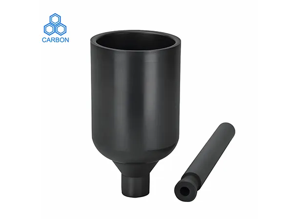
Choosing the right crucible for melting gold and silver is a critical decision that directly affects melt quality, operational efficiency, and equipment lifespan. Whether you run a jewelry workshop, a precious metals refinery, or a small-scale casting operation, the crucible material, size, and design must match your specific melting conditions. In this guide, we examine the most common crucible types, compare their performance characteristics, and explain how to make an informed choice. As a trusted manufacturer with years of industry experience, Cangzhou Carbon provides high-quality crucibles engineered to meet the demands of professional gold and silver melting.

Understanding Crucible Materials for Gold and Silver Melting

The base material of a crucible determines its temperature tolerance, resistance to thermal shock, and chemical reactivity with molten metals. For gold and silver melting, three main materials dominate the market.

Graphite Crucibles

Graphite crucibles are widely used for precious metals due to their excellent thermal conductivity and uniform heat distribution. They handle temperatures up to 2500°C (4532°F) and resist chemical attack from molten gold and silver. However, pure graphite is porous and can oxidize quickly in air, so a protective coating or glaze is often applied. Cangzhou Carbon graphite crucibles feature a dense, fine-grained structure that minimizes oxidation and extends service life.

Silicon Carbide Crucibles

Silicon carbide (SiC) crucibles offer superior thermal shock resistance and mechanical strength compared to graphite. They withstand rapid heating and cooling cycles without cracking, making them ideal for high-frequency induction furnaces. SiC crucibles also resist erosion from fluxes used in refining processes. Their higher cost is justified by longer lifespan in demanding applications.

Clay-Graphite Crucibles

Clay-graphite crucibles blend natural graphite with refractory clays, balancing thermal performance and affordability. They are suitable for medium-temperature melting (up to 1600°C) and are commonly used for silver and lower-temperature gold alloys. While not as durable as SiC, clay-graphite crucibles provide a cost-effective solution for small-scale or intermittent use.

Key Factors to Consider When Choosing a Crucible

Beyond material, several technical parameters influence crucible selection. Evaluate each factor against your specific melting setup.

For more information on how to choose a suitable gold and silver smelting crucible, please click to visit:https://www.czgraphite.com/a/news/crucible-guide.html

Extend Crucible Life: Anti-Oxidation Coating Explained

Industrial crucibles are subjected to extreme thermal and chemical stress. Oxidation at high temperatures gradually degrades the crucible material, leading to cracks, reduced strength, and early failure. Anti-oxidation coatings offer a proven solution to shield the crucible surface, significantly extending service life and lowering operational costs. This article explains how these coatings work, their key benefits, and practical considerations for selection.

The Oxidation Challenge in Crucible Operation

When graphite or silicon carbide crucibles are exposed to air at temperatures above 800°C, oxygen reacts with the carbon content, forming CO or CO₂. This continuous material loss weakens the crucible wall, reduces thermal conductivity, and eventually causes structural failure. In foundries, crucible replacement downtime can cost thousands per hour, making oxidation protection a high-ROI investment.

How Anti-Oxidation Coatings Work

Advanced anti-oxidation coatings create a dense, impermeable barrier on the crucible surface. These coatings typically contain ceramic or refractory particles (e.g., alumina, zirconia, or mullite) suspended in a binder system. When applied and cured, they form a physical shield that blocks oxygen diffusion while maintaining thermal shock resistance.

For more detailed information on antioxidant coatings that extend crucible life, please click to visit:https://www.czgraphite.com/a/news/crucible-coating-gui.html

Graphite vs Clay Crucible: Which Performs Better at 1600°C?

Selecting the right crucible for high-temperature metal melting or alloy production at 1600°C is a critical decision that directly impacts process efficiency, product quality, and operational cost. While both graphite and clay crucibles are widely used, their performance diverges significantly under extreme thermal loads. This article provides a rigorous technical comparison, equipping engineers and procurement professionals with the data needed to choose the optimal material for applications requiring sustained 1600°C performance.

Understanding Material Fundamentals: Graphite vs Clay Crucible

Graphite Crucible Composition and Structure

Graphite crucibles are manufactured from high-purity natural or synthetic graphite, often bonded with carbonaceous binders and fired at ultra-high temperatures. The resulting structure is highly crystalline, giving graphite exceptional thermal conductivity (typically 100–130 W/m·K) and low thermal expansion. These properties make graphite crucibles extremely resistant to thermal shock—a critical advantage when rapidly heating to 1600°C or cooling.

Clay Crucible Composition and Structure

Clay crucibles, also known as ceramic or refractory crucibles, are made from aluminosilicate clays (such as fireclay) blended with grog (fired clay particles) to reduce shrinkage. Their microstructure is more amorphous and porous than graphite. Thermal conductivity is low (around 1–3 W/m·K), meaning clay crucibles heat more slowly but provide better insulation. However, their coefficient of thermal expansion is higher, making them more prone to cracking under rapid temperature changes.

Key Performance Comparison at 1600°C

When operated continuously at 1600°C, the following factors determine crucible suitability.

For more information on whether graphite crucibles or clay crucibles perform better at 1600°C, please click to visit:https://www.czgraphite.com/a/news/graphite-vs-clay-crucible.html

Top 5 Signs Your Graphite Crucible Needs Replacement Now

In high-temperature metal melting operations, the graphite crucible is the unsung hero that directly impacts melt quality, energy efficiency, and production uptime. Yet even the highest-quality crucibles eventually wear out, and ignoring the early warning signs can lead to catastrophic failures, costly downtime, and compromised product integrity. Cangzhou Carbon, a trusted manufacturer with over a decade of experience in carbon and graphite products, emphasizes that proactive replacement based on observable indicators is far more cost-effective than reactive repairs. This article outlines the five unmistakable signs that your graphite crucible has reached the end of its service life and why immediate replacement is critical for your operations.

1. Visible Surface Cracks and Structural Damage

The most obvious indicator that a graphite crucible needs replacement is the presence of visible cracks, chips, or spalls on the crucible wall, rim, or bottom. Even hairline cracks can propagate rapidly under thermal cycling, allowing molten metal to seep into the crucible wall and cause leakage. When a crucible develops cracks wider than 1 mm or exhibits a network of fine fissures, it has lost its structural integrity. Continued use risks molten metal escaping into the furnace, damaging heating elements and requiring extensive cleanup. Inspect your crucible after each heating cycle—if you notice any through-wall crack or a crack that extends more than one-third of the way down the side, replace it immediately. Cangzhou Carbon recommends performing a visual inspection with a flashlight and a magnifying glass at least once per shift in continuous operations.

How to Differentiate Surface Damage from Normal Oxidation

Normal surface oxidation appears as a powdery gray layer that can be brushed off. In contrast, structural damage shows as sharp, linear fractures with clearly separated edges. If you press gently on a suspect area and the graphite flakes or crumbles, it is a sign of advanced degradation that warrants replacement.

2. Excessive Wall Thinning and Deformation

Over time, the wall thickness of a graphite crucible decreases due to erosion from slag, flux, and the abrasive action of molten metal. While a certain amount of thinning is expected, a reduction of more than 30% of the original wall thickness significantly compromises the crucible’s load-bearing capacity and heat conductivity. Measure the wall thickness at several points every 25–30 melts. If the difference between the thickest and thinnest points exceeds 2 mm, the crucible has become uneven and may warp under thermal stress. Warping often manifests as an oval shape at the top rim or a bulge near the bottom. A deformed crucible does not sit evenly in the furnace, leading to hot spots and uneven melting. At Cangzhou Carbon, our quality control team advises that any crucible showing measurable warping should be taken out of service—continuing to use it risks tipping over during handling or causing a splash of molten metal.

For more information on the five signs that a graphite crucible needs replacing, please click here:https://www.czgraphite.com/a/news/signs-of-graphite-crucible-replacement.html